Figure 1. Verify the RS232 connection.
Download and install LookRS232 (shareware) on the PC. Connect the PC to the Doppler Tuning Box as shown in figure 1.
Figure 1. Verify the RS232 connection.
| Pin | Level | Function |
| P6 | 0V | No test frequency generated |
| P7 | 5V | Enable LEDs |
Power up the Doppler Tuning Box. Run LookRS232 and set up the serial port by selecting File | Connection and setting 2400 baud, 8-N-1, no flow control:
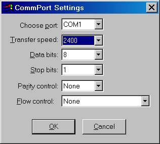
Figure 2. LookRS232 COM-port settings.
Type a single h in the Data Send Task pane. This will bring up the word hexadecimal. Now enter the digits as shown in figure 3. Click the yellow arrow to send.
Enter for example FE FE 14 E0 15 21 83 29 35 04 FD. The frame format is correct, but the command-byte is wrong (should be 05 instead of 15). If the RS232 connection works, the frame will be received and discarded by the basic stamp, and the red LED will flash. Send the frame several times - the red LED will flash every time. This confirms, that the RS232 connection is working.
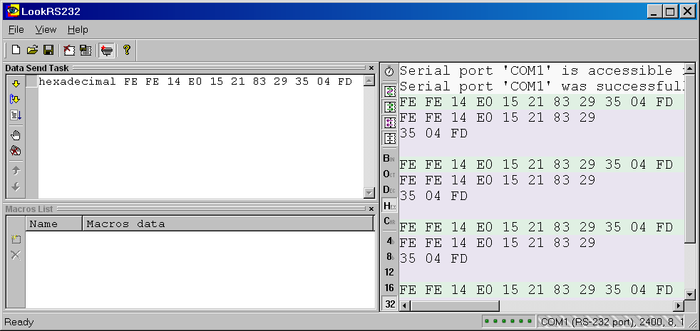
Figure 3. Sending frames with wrong command-byte to the Doppler
Tuning Box..
Now send a frame with correct cmd-byte (05), for example FE FE 14 E0 05 21 83 29 35 04 FD. The green LED will flash once. If you try to send the frame for the second time, no LED will flash, because there has not been any change in frequency data (that is 100 Hz, 1 kHz, 10 kHz, 100 kHz have not changed).
Figure 4. Tracing output from WispDDE.
Open LookRS232 and configure the serial port by selecting File | Connection and setting 2400 baud, 8-N-1, no flow control (see figure 2).
Orbitron and WispDDE are now enabled, and the output from WispDDE is monitored as seen in figure 5 below. The Data Send Task and Macros list panes are closed. The first frame is FE FE 14 0E 0F 00 FD (at timestamp 28.681). The preamble (FE FE) is OK, but the command-byte is wrong (is 0F, should be 05). The next frame is correct: FE FE 14 0E 05 93 81 29 35 04 FD, and so are all the following frames.
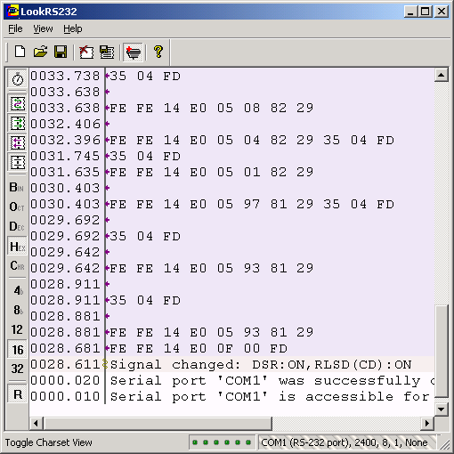
Figure 5. Receiving frames from WispDDE.
Conclusion: The RS232 output generated by WispDDE is usable for the Doppler Tuning Box.