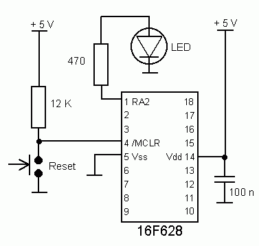
Testboard K4 configured for 628LED.asm
Hardware
The testboard K4 is set up with
reset circuit and a LED.
Note: RA4 (pin 3) has an open drain output. It cannot supply power to an external circuit. If a LED is connected to this pin, it must be connected like this: LED cathode to pin 3, LED anode to resistor, resistor to +5V.

Testboard K4 configured for 628LED.asm
Software in assembler
;************************************************************
; Processor: PIC16F628
at 4 MHz using internal RC oscillator
; Function: Flash
a LED connected to RA2
; Hardware: Testboard
K4
; Filename: 628LED.asm
; Author: Lars Petersen, oz1bxm@pobox.com
; Website:
www.oz1bxm.dk/PIC/628LED.htm
; Credit:
Tony Nixon's LED flasher
;************************************************************
LIST P=16F628, R=DEC ; Use the PIC16F628 and decimal system
#include "P16F628.INC" ; Include header file
__config _INTRC_OSC_NOCLKOUT & _LVP_OFF & _WDT_OFF & _PWRTE_ON & _BODEN_ON
CBLOCK 0x20
; Declare variable addresses starting at 0x20
Loop1,Loop2
ENDC
;
; -----------
; INITIALIZE
; -----------
;
ORG 0x000
; Program starts at 0x000
CLRF PORTA
; Initialize port A
CLRF PORTB
; Initialize port B
BSF STATUS,RP0 ; RAM bank 1
CLRF TRISA
; All pins port A output
CLRF TRISB
; All pins port B output
BCF STATUS,RP0 ; RAM bank
0
;
; ------------------------
; FUNCTION OF PORT A
PINS
; ------------------------
;
MOVLW 7
MOVWF CMCON
; Comparators off, all pins digital I/O
;
; ----------
; MAIN LOOP
; ----------
;
Main
BSF PORTA,2
; Turn on LED connected to RA2
CALL delay
BCF PORTA,2
; Turn off LED connected to RA2
CALL delay
GOTO Main
;
; ---------------
; DELAY 250 MSEC
; ---------------
;
delay MOVLW
250
MOVWF Loop1
Outer MOVLW
200
MOVWF Loop2
Inner NOP
NOP
DECFSZ Loop2,F
GOTO Inner
; Inner loop = 5 usec.
DECFSZ Loop1,F
GOTO Outer
RETURN
END
Remarks
The parameter _INTRC_OSC_NOCLKOUT
makes
the PIC use the internal 4 MHz RC oscillator. This means, that RA6 and
RA7 are available for I/O.
The CMCON register is loaded with value 7 for all portA pins to function as digital I/O.
The reset function of pin 4 (RA5) can be disabled and the pin configured as an input pin. This is done by specifying _MCLRE_OFF in the _config line.
All ports can be toggled by substituting
the main loop with the following lines:
;
; ----------
; MAIN LOOP
; ----------
; Apply 2 Hz to all
ports
Main
MOVLW b'01010101'
MOVWF portA
MOVWF portB
CALL delay
MOVLW b'10101010'
MOVWF portA
MOVWF portB
CALL delay
GOTO Main
Download
Download 628led.zip
containing the source code in assembler and the hexfile.
Credit
Tony Nixon's LED flasher at http://www.piclist.com/techref/microchip/16F877/flashled.htm
inspired me. Thanks!