August 15, 2012 - New blog platform
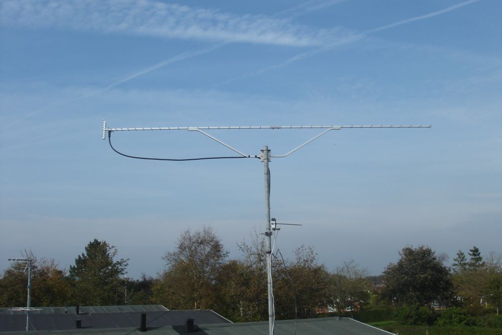
This blog moved to the Blogspot platform. Please update your bookmarks! New blog address: oz1bxm.blogspot.dk. The new platform supports feeds and has a reply function. August 2012 - New yagi for 10 meters My new, rotatable beam antenna for 10 meters is a 2 element yagi manufactured by Innovantennas in the UK. The version is called OP-DES (Opposing Phase Driven Element System). The OP-DES has the ends of the dipole bent back towards the reflector element. This shape provides 2 functions: Firstly, the current phase in each end section is in opposing phase and therefore cancel one another out, this helps to reduce/remove side lobes. Secondly, these end sections act as impedance controllers and thus making the adjustment of the antenna easier. 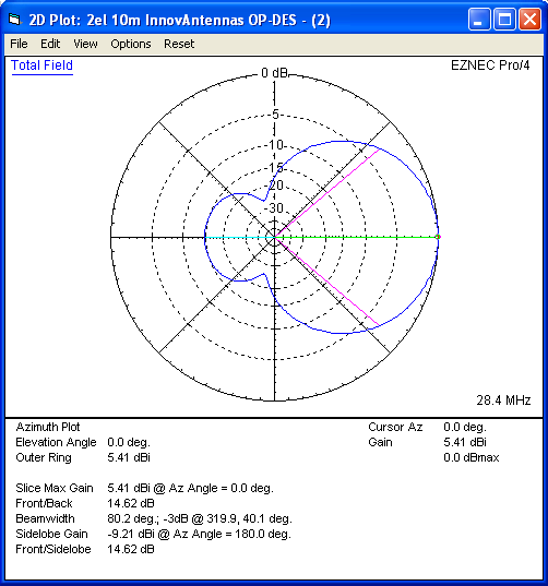 Radiation from the 2-element yagi at 28 MHz. July 2012 - Working 3A Monaco In the late evening of May 19th I saw 3A2LF calling CQ on 14.076 MHz, and I clicked immediately the Answer CQ button in JT65-HF. He came back to me and we had a standard QSO. As I did not expect anything unusual this evening, I was just happy to log a new country. Monaco is the second smallest country of the World. Only Vatican City is smaller. Monaco is a city state of 2 km² and located on the French riviera. The population of Monaco is 36,000 and the country is governed under a form of constitutional monarchy with Prince Albert II as head of state.  3A - Monaco. 3A2LF Claude prefers paper-QSL, so I sent him a traditional QSL plus SAE and one IRC. Some weeks later a nice letter from Monaco arrived in the mail. Click to see the card from 3A2LF. June 2012 - The cow on the card The invention of the electronic QSL is a great achievement. Remember the old days (not long ago), where hams could wait one or two years for a QSL card to arrive via the bureau system? Today, electronic QSLs are exchanged fast and convenient, often within days or even within the minute! I received the nice QSL below just 2 days after I had a QSO with Leslie on Jersey Island. And being the son of a farmer, I really appreciate the cow on the card.  QSL from Jersey Island. From Wikipedia: "Jersey Island is the home of the Jersey cattle. Jerseys are well known as curious and gentle cattle. They are also highly recommended cows for first time owners". May 2012 - My ham radio shack There are two small rooms in our house. One of them is used by my wife, the other one by me. My room is mainly used as ham radio shack and "Father's office". Due to it's small size, I have to keep the room tidy. Only one or two radios are placed on the table next to the PC monitor. 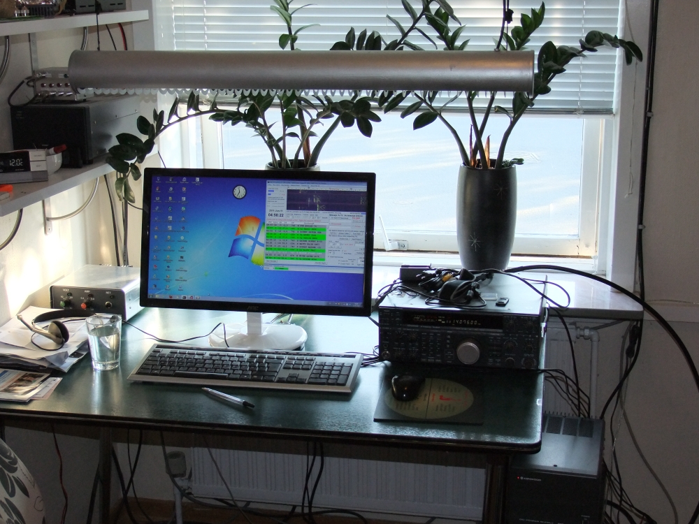 Ham radio shack of OZ1BXM. Fortunately my shelves provide space for SWR-meters, a Power Amplifier for 2 meters, rotor controllers, and other nice boxes. Spare parts and electronic components are also found on the shelves. Cables and connectors are housed in open plastic boxes. A cupboard stores many treasures like frequency counters, an LC-meter, a soldering station, different pre-amps, different power supplies, boxes for QSL cards, and so on. A small collection of hand tools is also found in the cupboard. Some older radio shack pictures are here. April 2012 - Springtime in Denmark The outdoor temperature in Holstebro is rising and can often reach 10º C (50º F) during daytime. Winter has passed and spring is coming. The days are becoming longer, and everyone loves it. Many start thinking about their summer holidays. I am not a garden lover, and I let my XYL do all the gardening. She keeps the garden, and I look after the antenna farm. I don't intend to switch that scheme! 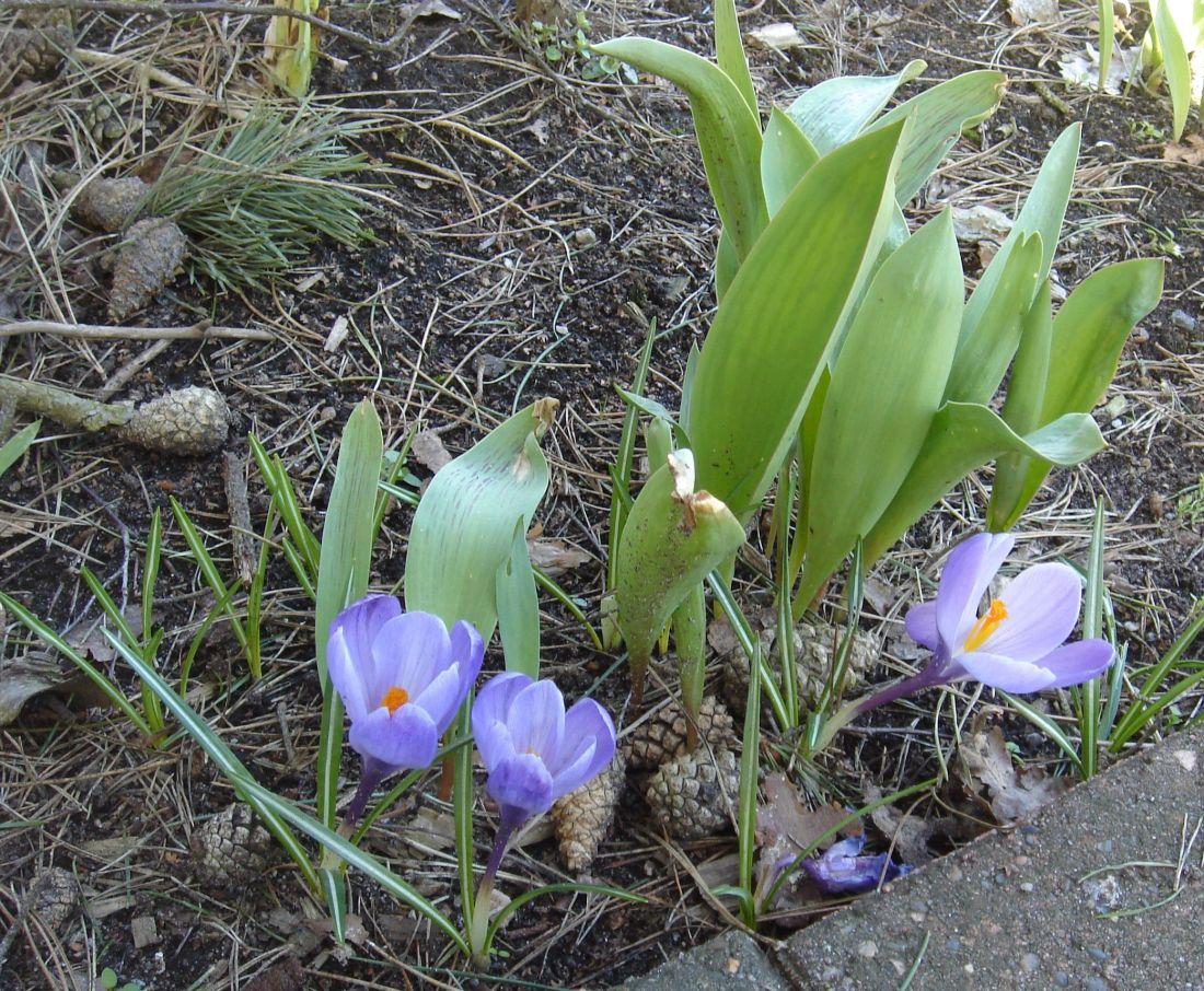 Early flowers (crocus vernus) in our garden. I'm planning some antenna work during the Easter holidays. I have purchased a new antenna, which should help me work more DX. I'll come back to that in a later installment. March 2012 - A hard nut to crack WAZ (Worked All Zones) is a classic ham radio award sponsored by CQ Magazine. I have been chasing WAZ for several years and I have worked 39 of the 40 zones. Only zone 6 is missing in my collection. I would have expected some remote zone in the Pacific to be the most difficult one to work, and not this one. 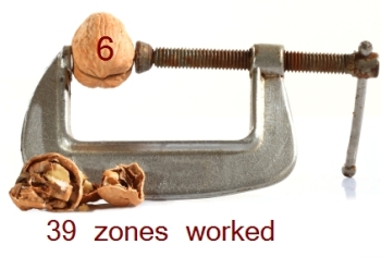 CQ zone 6 is a hard nut to crack. Why
is zone 6 so difficult to work from Denmark?
The nearby entity of California is easy to work from OZ
when conditions are good. Is the majority of the XE hams living
in Mexico City, which is 2500 km (1550 US miles) SE of Los
Angeles? Is propagation different at this distance? Please write to me if you can explain this phenomen!(picture credit: www.happyschoolsblog.com) February 2012 - Clublog My logging program is DXKeeper, which is free software and contains no advertising. DXKeeper has a myriad of functions, but is not suited for displaying on a web page. This is where Clublog comes into the picture.  The Clublog logo. Clublog is a free web-based tool for producing DXCC tables, log search services, and most-wanted lists for ham radio. You upload an ADIF-file (containing your log) to Clublog. You can then analyze your log and watch your DXCC and WAZ status on the Clublog page. By adding some HTML-code to your homepage or QRZ page, you can implement log search and other useful tools. I've decided to show my 10 latest QSOs and make log search available. January 2012 - Contest participation I participated in two contests last year: CQ WW CW and the ARRL 10M contest. My goal was to work the zones I needed for completion of WAZ. However, zone 6 still remains unworked after the contests. Logo of the CQ WW contests. Three contest weapons were included in my contest effort. The first one was Spot Collector by DXLab. This application connects to different DX clusters around the world and it can display spots in many ways. I created customized filters for the zones I was looking for. The second weapon was HamCAP by Alex Shovkoplyas VE3NEA. HamCAP is a HF propagation prediction tool for Amateur Radio. Ionospheric data are gathered in real-time via IonoProbe. A nice feature is the best hour chart, where the optimal propagation hour is displayed for each band. I also appreciate the area coverage map. The third weapon was Winwarbler by DXLab. This application is normally used for operating digital modes but in my case it served as a CW sending machine. Winwarbler was connected to my Kenwood TS-850 via CAT interface, and the TS-850 ran break-in keying. December 2011 - Keeping the old horse running My HF-transceiver is a Kenwood TS-850. I bought it second hand some years ago, so I don't know its entire history. Its low serial number indicates a product about 20 years old. The transceiver's output began to cycle up and down and at the same time ALC went from zero to max. This is a common TS-850 problem: unstable ALC voltage. What to do now? 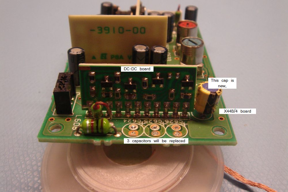 Repairing ALC problem in Kenwood TS-850. I took off the TS-850 lid and located the X44B/4 board under the loudspeaker. I loosened three edge-connectors and 4 screws in order to lift it up and place it on the workbench. Four electrolytic capacitors on the X44B/4 board were replaced, and two resistors on the tiny DC-DC daughter board were changed from 22 kohm to 18 kohm. That solved the problem. The TX output is now normal again due to stable ALC voltage. Thanks to G4IFB and N6TR who runs The TS-850 Repair Page. The old horse is still running! November 2011 - 23 cm antenna My new 23 cm antenna is SHF 2344 from Wimo. This 44 element yagi antenna is 3 m long and is easy to assemble as all elements are mounted at the factory. The reflector has 8 elements securing an excellent front/back value. The cable between antenna and transverter is Ecoflex 10 terminated with N-connectors. 23 cm yagi antenna with 44 elements. Long yagi antennas employ a narrow beam pattern and it's important to aim the antenna exactly. This is the price to pay for enjoying large gain. The claimed gain of this antenna is 18.1 dBd (20.2 dBi) and the beam pattern is 16° wide. October 2011 - Lassen Sie sich begeistern! The headline is a quote from the opening speech given by DL4ZAO at the VHF Convention in Bensheim, Germany. It means: "Allow yourself to have fun". Besides the challenges of the technical stuff, hams should have fun. This will attract new members to the ham clubs and other ham societies. I had a pleasant time at the convention. The flea market offered all sorts of equipment and components. I bought a small alu cabinet, an analog meter, a log-periodic antenna 900-2600 MHz, and some teflon patch cables. I could have purchased much more as the selection was huge! At the Kuhne Electronic booth, I picked up a power supply and a sequencer for my 23 cm transverter. There were plenty of speeches covering a variety of subjects. One of them was by OZ2M Bo Hansen who lectured on "Next generation beacon platform". The picture below is from that session. 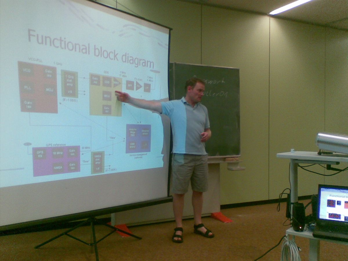 Lecture by OZ2M Bo Hansen. September 2011 - VHF Convention in Germany I'll go to Bensheim (near Frankfurt) in Germany on 9.-10. September to participate in the VHF convention there. This convention was earlier held in Weinheim. Hams from all Europe will meet and listen to speeches, visit a large exhibition of ham radio equipment, take a look at the flea market selection, and so on. I'll tell more in a later blog entry. Logo of the VHF Convention. August 2011 - Alignment of 1296 MHz transverter In order to align my Kuhne transverter kit, I've bought a signal source kit with output on the 23 cm band. The signal source is designed by OZ2M Bo and it works as a comb generator. The source is based on a 16 MHz crystal oscillator followed by BAT45 which is a diode creating the harmonic frequencies. The 81th harmonic is at 1296.000 MHz. Inside view of signal source. The "Milli-Beacon" signal source. The signal source is battery powered and provides a stable signal for trimming the receive part of the transverter. The transmit part was adjusted using a multimeter and the transverter's output monitor. July 2011- When twilight lasts all night Twilight is when sunlight scattering in the upper atmosphere illuminates the lower atmosphere, and the surface of the Earth is neither completely lit nor completely dark. The Sun itself is not directly visible because it is below the horizon. During the summer, twilight is present all night long in Denmark. In my hometown Holstebro, this phenomen occurs for 3 months every year starting May 4th and lasting until August 8th. It is an amazing time as the nights never really get dark. Complete darkness occurs when the Sun is more than 18 degrees below the horizon, and this is never the case during that period. The picture below shows the passing of July 1st in Holstebro, Denmark. When darkest the Sun is never more than 12 degrees below the horizon. 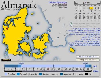 Twilight July 1st in Denmark. Click to enlarge. The danish word for twilight in summer nights is "lyse nætter" (bright nights). During this time, many people relax outdoors in the garden until late, or they enjoy camping life and music festivals. June 2011 - UK hams celebrate royal wedding Beginning April 29th and the following 3 weeks, UK hams could use special calls which included an "R" (Royal). The special event was the royal wedding in London. I worked MR6FUN on 20m some days after the wedding. MR6FUN is in Bristol, and he used 5 W and a magnetic loop antenna. You can see his beautiful QSL-card below.  QSL from MR6FUN. Click to enlarge. People may have different opinions on royal families and their role in a democracy. But this event was known world-wide, and it provided an opportunity to promote ham radio. The QSL-card plays a key role. Showing it to others and explaining how you got it can open people's eyes on the wonderful world of ham radio! May 2011 - Preparing 1296 MHz activity I attended a conference in Ringsted, Denmark in late February. It was a conference for VHF/UHF and microwave enthusiasts. One of the presentations was called "How to become active on 1296 MHz and up". The presenter was OZ2LD and he described equipment and antennas ranging from 1296 MHz to 10 GHz. I became inspired and I have now decided to prepare activity on 1296 MHz. 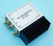 1296 MHz transverter from Kuhne Electronic (factory photo). I am currently building a transverter kit: MKU 13G2B KIT from Kuhne Electronic. RX/TX is from 1296 to 1298 MHz, and IF is on the 2 meter band 144-146 MHz. A yagi antenna from Wimo (SHF2344) is also a part of my plans. As there is little activity on the 23 cm band in Denmark, I have created a 1296 MHz page where I'll share my operational experience. April 2011 - New rotor controller My current rotor controller is the EA4TX ARS, which runs off the parallel port of the PC. I've been looking for a replacement lately because I wanted a serial or USB interface to the PC. The Easy Rotor Control (ERC-3D) by DF9GR seems like a good choise. It uses a serial link, it is sold as a kit, and the price is right. I've housed it in an alu-box, which earlier was used for another project. This is why some extra holes are found in the rear plate. I don't mind - the rotor controller is only used by me and I can live with that. You can take a look inside the box here. 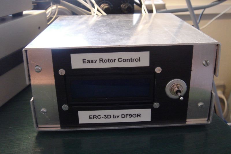 ERC-3D rotor controller. The LCD display on the front is bright and nice, and manual rotation is easy because you can monitor azimuth and elevation at the same time. I am satisfied with the performance of my new ERC-3D controller. No problems so far. March 2011 - A rusty rotor Time for maintenance of my Kenpro KR-500 elevation rotor. The potmeter inside the rotor serves as a heading indicator, and it needed replacement. First thing was to take apart the rotor housing. However, this task showed more difficult than anticipated. 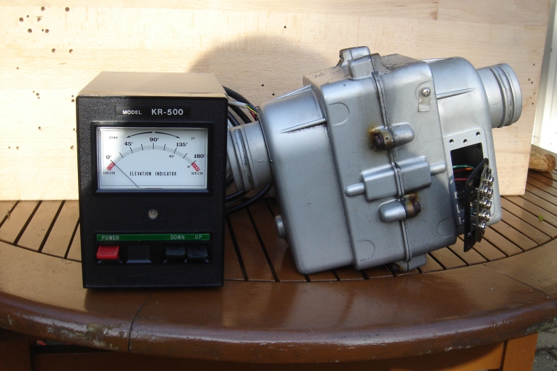 Kenpro KR-500 elevation rotor with rusty bolts. The housing of this rotor is bolted together as you can see in this picture. But I was not able to loosen any of the 8 bolts due to rust. I tried to spray them several times with WD-40 (a multi-purpose lubricant) but to no avail. Something had to be done. So I decided to sell the rotor as a do-it-yourself project. The asking price was 90 USD all items included. Fortunately, several hams responded. The rotor and control box has now got a new owner, and I have started looking for a new rotor (without rust, that is). February 2011 - The PicoKeyer Plus The PicoKeyer Plus from Hamgadgets is a battery-powered iambic keyer with small physical dimensions. It has 4 message memories which hold up to 60 characters each. The keyer can insert and increment contest numbers in a message and it can use cut numbers (sending N instead of 9, and T instead of 0). Transmitter QSK delay compensation is available. The keyer comes as a kit together together with an enclosure (option). I drilled 4 holes in the small plastic cabinet before mounting the PCB. The speed knob and the function push-button is on the front. Paddle input and keying output is on the rear. The picture below shows the PicoKeyer Plus and an AAA battery. 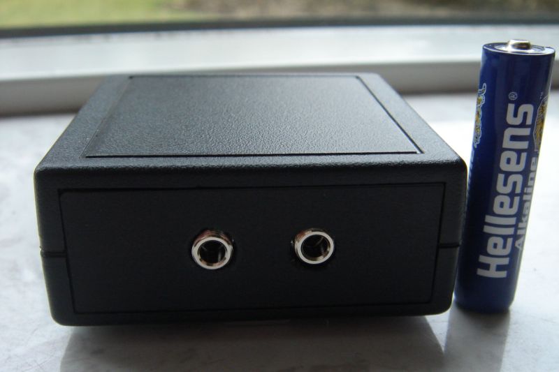 PicoKeyer Plus (rear view). My experience with the PicoKeyer Plus has been good. The keyer is easy to program, and has perfect timing in iambic mode A. My old "CMOS Super Keyer III" had timing issues in that mode. The Picokeyer has now become my preferred keyer. January 2011 - A Christmas gift to store My wife gave me a nice present this Christmas: a Passport Essential portable harddisk with 500 GB capacity. You can see it in the picture below - it is only the size of a passport and it easily fits into your shirt pocket! The only connection to the PC is a short USB-cable which carries both power and data. 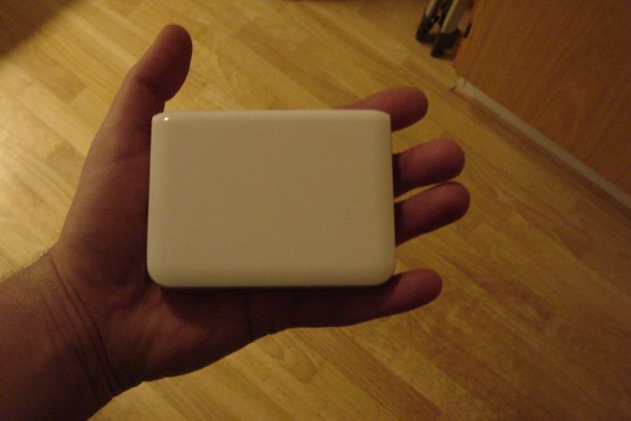 500 GB portable harddisk. I am very happy with this gift. It becomes more and more important not to loose any data. Data files have become indispensable in our modern life! December 2010 - Helping new hams I've created a homepage in Danish aimed at those who want to become radio amateurs. The objective is to teach the subjects required to pass the test and obtain a Danish novice certificate (category D). This certificate allows activity on the 50 MHz, 70 MHz, 144 MHz, 432 MHz and 1240-1300 MHz bands using 50 W output. The homepage contains instruction videos and multiple choise questions. As far as the videos are concerned, I enjoy getting into video recording and editing. It is fun to learn new skills! My camcorder is the Canon FS200 with external mic input. I use Windows Movie Maker for editing the footage. This application provides nice editing functions, and it is free! November 2010 - Quad antenna for 2 meters I have decided to buy a quad antenna for 144 MHz. The reason is mainly, that quads have shorter booms and more gain than yagi antennas with the same number of elements. This can be seen in the table below, which displays factory data of different antenna types.
It is my plan to compare the two antenna types on the air and I'll report my results later. Right now, antenna work is put on hold. October 2010 - First MS QSO confirmed I received a nice QSL card from HA8CE two weeks after my very first Meteor Scatter contact. OM Pista was running 1 kW from a homemade amplifier and he used 4 x 8 element yagis. He had an excellent signal. You can see his card in the scan below. 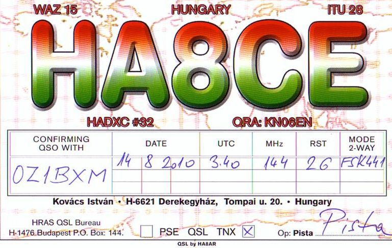 HA8CE confirming MS QSO. I used 150 W and an 8 element yagi for the QSO, which took place during the Perseids in August. The next major meteor shower will arrive later this month: The Orionids. September 2010 - My first MS QSO The picture below is a screen-dump from WSJT7, the program running on my PC and enabling me to make contacts in FSK441. I entered the ON4KST chat and found HA8CE. We called each other, and soon the QSO was complete. Much easier and quicker than I thought! You may click the picture below to read all details of the QSO. 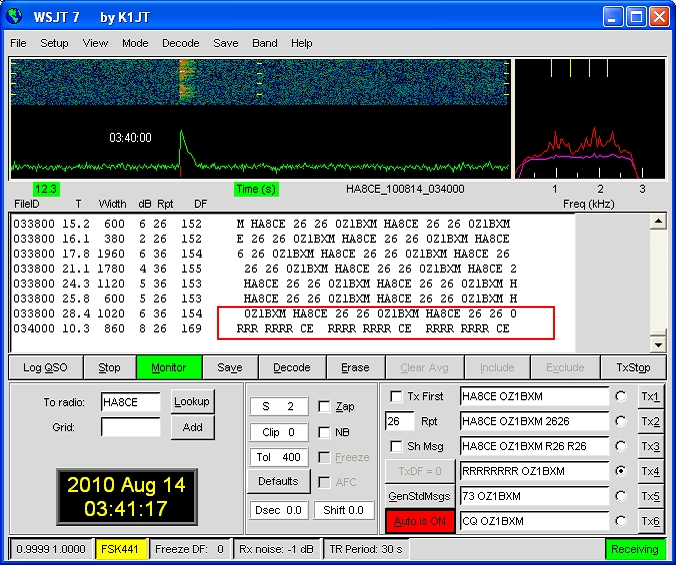 OZ1BXM in MS QSO with HA8CE An MS QSO must contain 4 elements: My call, His call, His report to me, His confirmation. You can find all elements in the picture:
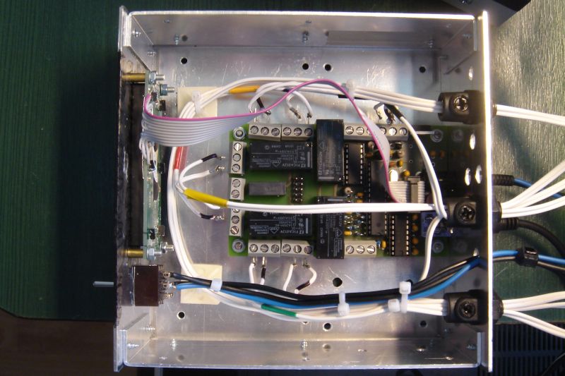
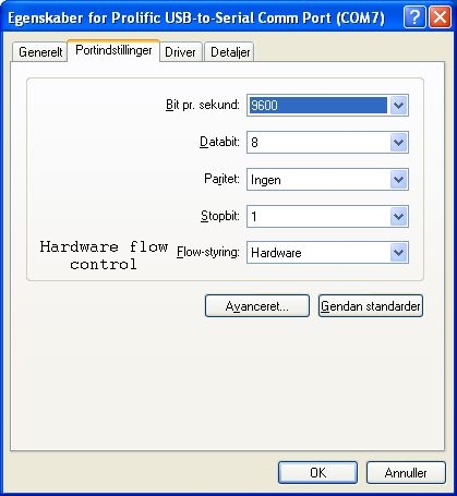
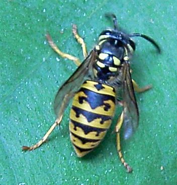
August 2010 - 2m brick amplifier Meteor scatter operation is possible running the transceiver barefoot (50 W), but it helps to have more power. I found this 170 W brick amplifier from RF Concepts online. It was sold as second-hand equipment at the site brugtgrej.dk. This site is being visited by many Scandinavian ham radio enthusiasts for trading of used equipment. 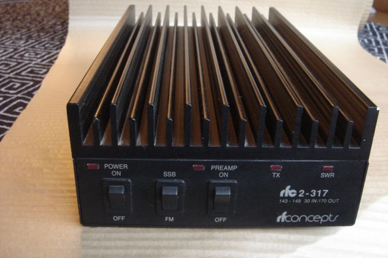 170W PA from RF Concepts. I am looking forward to write more on the subject Meteor Scatter next month. And I hope to have some QSOs to report! July 2010 - Data interface My Yaesu FT-847 transceiver needed a data interface because I plan to run WSJT and use the FSK441 mode for Meteor Scatter operation. I found a clever data interface described by DJ4UF. The interface employs 3 audio cables, one RS-232 cable, and 5 components, which are mounted inside an alu-box. The interface is pictured below. 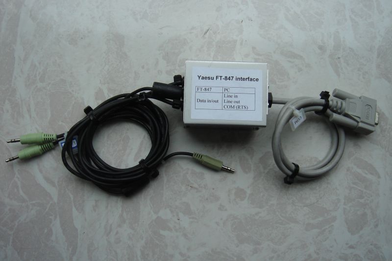 Yaesu FT-847 data interface. The audio connection between the transceiver and the PC worked immediately. However, I had some problems getting the TX signal work properly. The FT-847 would not switch to TX. Troubleshooting was done and here is what I learned. The cabling between the interface box and the COM-port must be corrrect. It sounds obvious, but I had two wires connected wrong. The COM-port configuration must include "Hardware flow control" (screen dump). Finally, no "funny" drivers should be associated with the COM-port. I removed a port driver previously used by Ham Radio Deluxe. The interface now works flawlessly. June 2010 - Preparing for Meteor Scatter Recently, I have caught interest in a new propagation mode: Meteor Scatter (MS). The picture below (credit to jt6m.org) shows how it works: Station A points his beam antenna towards station B. A meteor trail (ionized trail) 100 km above the earth's surface reflects the signal, so the distant station can be worked. The range for meteor scatter is 500 km - 2200 km. The two bands often used for MS are 50 MHz and 144 MHz. 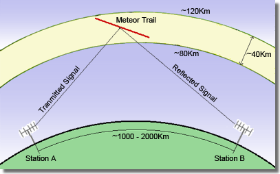 The radio signal is bounced off the meteor trail. The equipment can be modest - just 50 W and a beam antenna is enough for making contacts. I am planning to use my current equipment (Yaesu FT-847 and 8-element yagi) and try some MS QSOs on the 2 meter band. May 2010 - A strange place to nest Two weeks ago, I entered the attic to check my coax-cables. The cables escape the house via slots in the brick wall. Much to my surprise, I discovered a wasp's nest hanging from one of the coax-cables (see photo). Obviously, the wasps had entered through the slot and transformed a piece of coax-cable into a nest site. The nest was empty as I removed it. I don't want other wasps to find the old nest and start raising a new family! 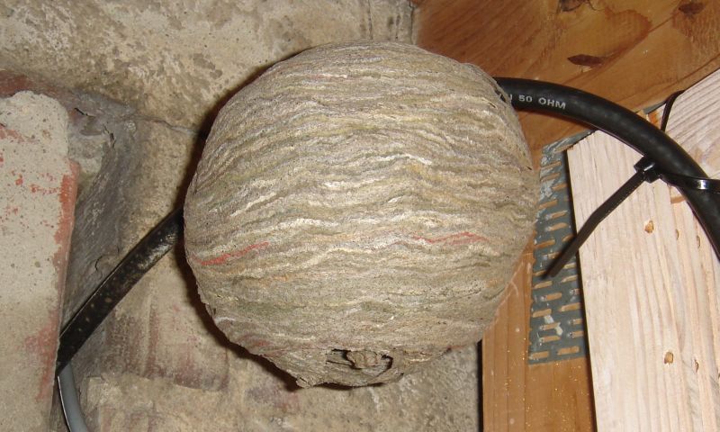 The wasp's nest. A wasp's nest is made from chewed wood fibres, mixed with saliva. The nest I found had a diameter of 12 cm (5 inches). Click the following link to view a picture of a wasp (Vespa vulgaris). April 2010 - My experience with D-Star I have used D-Star for some time now. It has been a different experience compared to analog FM on the 2m and 70cm bands. There are few users. The number of registered D-Star users in Denmark right now is about 150. There can be silence on the channels for hours. The D-Star audio quality is excellent with a clear voice reproduction. There is no trace of that machine-like voice, you can hear on some YouTube clips containing D-Star recordings. The D-Star logo. The communication range is large as all danish D-Star repeaters are interconnected via a reflector. You can speak to fellow hams hundreds of kilometers away. This linking creates a "national repeater". As more D-Star repeaters will be put into service, the "national repeater" will cover every corner of Denmark. All repeaters have channnels covering the local area and by selecting a local channel you avoid having your QSO be overheard nationwide. The satellite OUFTI-1 will use DV (Digital Voice) for up- and downlink. I am looking forward to use D-Star via a LEO satellite. OUFTI-1 is scheduled for launch in October 2010. March 2010 - My first D-Star radio The new D-Star protocol, which was developed by JARL (Japan Amateur Radio League), makes radio transmission and reception purely digital. This is a major change and will impact ham radio in the long term. I believe D-Star will upgrade and broaden the way hams communicate just like when we shifted from CW to phone. Here are the major benefits of the D-Star protocol:
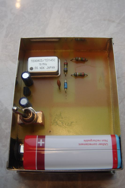
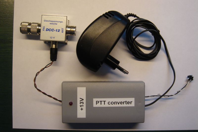
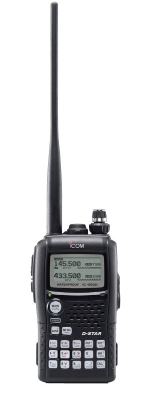 Icom IC-E92D portable D-Star radio. To explore D-Star, I've bought a portable dual-band radio: Icom IC-E92D. It has D-Star built in from the factory and it can be used for FM and DV right away. It works on the 2 meter band and on 70 centimeters. I'll write more about my experience with D-Star next month. February 2010 - Reaching worldwide with WSPR The WSPR protocol is highly efficient when it comes to reaching distant places. The signal-to-noise ratio can be as low as -30dB or less at the receiving end. On January 25th I let my transmitter broadcast WSPR both night and day on the 40 meter band with 5W output. The antenna was the loop skywire as described on this blog in December 09. I visited http://wsprnet.org at 10:00 AM to see how far my signal had reached. Much to my surprise, all continents were "worked". I write "worked" because WSPR spots do not count as QSOs. The map below shows the spots from that day. 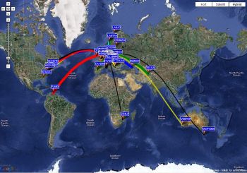 All continents "worked" with WSPR on 40 meters. The blue labels on the map indicate where my signal was received, or the labeled station was received by me, or both. If you click the label, an info box pops up and displays this information. Even semi-rare DX stations can be found on 40 meters using WSPR. If you click on the image above or this link, you can read how ZK1AGG/P in Rarotonga, South Cook Islands received my 5 W signal later on the same day. January 2010 - PC hardware upgrade Four years have gone since I last upgraded my PC. Now it is time for new hardware. I found an upgrade kit in a webshop at 150 Euro. The kit consisted of a micro-ATX motherboard (Asus M2A74-AM SE), a dual-core processor (AMD Athlon II X2 240) with CPU cooler, and 2 Gbyte DDR2 RAM. I added a video card (Asus EAH4350 Silent) and a harddisk (640 Gbyte Samsung HD642JJ). 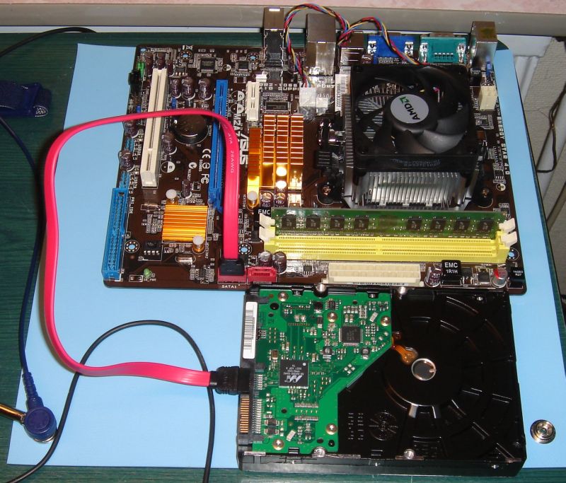 PC hardware ready for testing. There was a problem during assembly of the PC: The new Samsung harddisk worked extremely slow. First, I tried to update the Asus BIOS to no avail. Then I googled the harddisk and found a firmware upgrade. Having installed that upgrade, everything worked normally for a while. Suddenly the throughput of the Samsung harddisk went down from 100 % to 2 %. Eventually, I changed the motherboard from Asus to the Gigabyte GA-MA770-UD3. The new motherboard solved the problem. I am now happy with my DIY PC. December 2009 - Loop skywire antenna I have considered which antenna would be best for DX and at the same time fit into my small garden. The loop skywire is the best kept secret in the amateur circle according to The Loop Skywire (QST November 1985). As 40-50 meters of wire can be accommodated on my suburban lot, it was an easy decision to give this antenna a try. My loop skywire antenna is 43 meters long and erected horizontally to the earth. It is supported in 4 corners and the feed-line is connected to one of them. The antenna resonates in the 40 meter band but is usable on the higher bands as well. 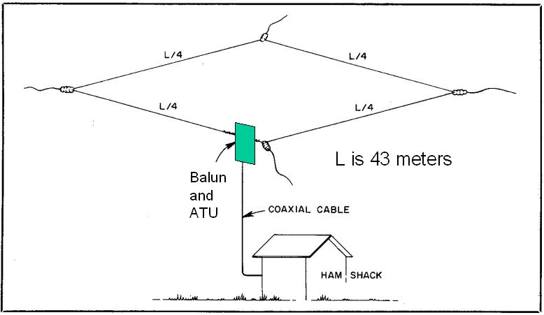 Loop skywire at OZ1BXM My loop skywire is shown in the picture above. The wideband balun is a BL2 from Elecraft and the ATU is an SG-239 Smartuner from SGC. They are both enclosed in the same plastic box which is placed at the antenna feedpoint. November 2009 - WSPR I'll introduce WSPR this month. WSPR means Weak Signal Propagation Reporter. This software turns your ham radio station into a manned beacon station that can both receive and transmit. Let us begin receiving. The software runs on a PC and uses the soundcard for decoding audio signals received by the radio. The audio is encoded in MEPT_JT which is a protocol developed by K1JT. The signal is FSK with bandwidth of only 6 Hz. Each transmission lasts 2 minutes and contains call, locator, and power output. The signal can be very weak (inaudible) and still be detected. The power level used by transmitting stations is typically between 1W and 5W.  WSPR receiving The screen-dump above shows some WSPR stations detected at my QTH on the 40m band during a Friday evening. The (temporary) antenna was just 10 meters of wire tossed on the roof. October 2009 - Morse Runner Last month I introduced the free software application "Morse Runner" by VE3NEA, Alex. You can see the GUI below:  Morse Runner by VE3NEA I have been using Morse Runner almost every day during the last month. I have found three advantages using this software: 1. My cw receiving ability has improved. My receiving speed (single calls) was 15 WPM when I started the training 4 weeks ago. Today, I can receive calls and reports at 21 WPM. 2. My cw sending speed has increased. This is mainly due to using the keyboard. Earlier, I used to send cw with a paddle and an electronic keyer. The keyboard, however, enables me to send much faster and without errors (except for typos). A nice side effect using a keyboard is the additional time you gain compared to manual keying. The secret is the use of macros. When I receive a call and type it in the "Call" field (for example SM5REA), I simply press a single key and the software sends SM5REA 599 012. Meanwhile, I can just relax. I find it easy to sip coffee in the middle of a QSO! 3. The sound picture provided by Morse Runner is highly realistic. You get a genuine 'radio feeling' when sitting in front of the computer wearing headphones. September 2009 - Improving my CW skills My CW skills need to be improved. I need to be more confident at typing calls at the keyboard, and thus perform better when contesting. I've found some nice and free software for this task: Morse Runner by VE3NEA. It runs under Windows or Linux. You can download it from Afreet Software, Inc. Morse Runner is freeware. Morse Runner can simulate a contest environment with QRM, QRN, QSB, flutter, and LIDs. It sends single calls or several calls at the same time (pile-up). I like this software. Thanks to Alex Shovkoplyas for developing it and making it available for everyone! August 2009 - AO-51 celebrates the first Man on the Moon Neil Armstrong was the first person to walk the surface of the Moon. He was followed by Buzz Aldrin shortly after, while Michael Collins had to stay in the orbiting Command Module. All this happened 40 years ago on the 20th of July 1969 (21th of July European Time). I was 11 years old that summer. All three men deserve honour and respect together with the huge number of people who made Apollo 11 a succes. 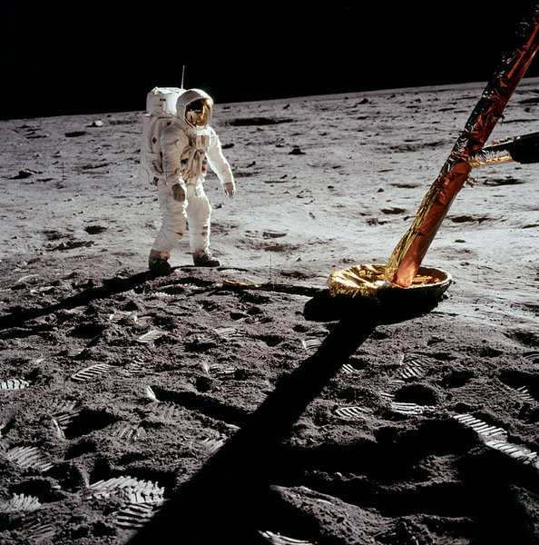 Buzz Aldrin on the Moon AO-51 transmitted a special message during 20-21 July 2009 to celebrate the 40 year anniversary of the first Moon landing. You can hear my recording by clicking this link. There is some fading because I used a linear 70 cm yagi antenna, but the famous words by Armstrong can be heard between 00:54 and 01:04. A better audio quality is found in a recording made by KL7UW. July 2009 - Keying the 23 cm transmitter My 23 cm transmitter is the MKU 13 OTX up-converter from Kuhne Electronic. Keying is done by applying +12V to the converter, either to an external terminal or via the coax cable. As the converter is sitting near the antenna, I prefer keying via the coax. To support this function, I have acquired a bias tee (DCC-12) from SSB Electronic. When applying 12V to the phono socket, it sends 12 V up the antenna cable, but protects the transceiver from getting DC into the antenna connector. 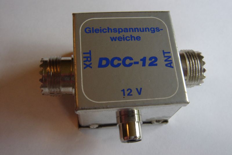 Bias tee from SSB Electronic. As
my Yaesu FT-847 transceiver provides active low keying via
the STAND-BY socket on the rear panel, I had to convert active low
to active high. A few
components were assembled on a PCB and put into a plastic box. You can
click to view a picture of the whole assembly. The circuit diagram is here. A picture of the open box is here. June 2009 - New 13 cm antenna
My old 13 cm antenna can be seen in
the picture below. It is a homemade 5-turns helix antenna. The helix
itself is made of copper wire. It has provided good service as
a beginners antenna. Pointing the antenna towards the
satellite is not critical, as the radiation pattern of the antenna is quite
broad.
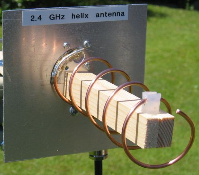 Homemade
5-turns helix antenna for 13 cm
My new 13 cm antenna is a 21-turns helix from Wimo (Helix13). You can see how small it is in the picture below, it's only 80 cm long. The helix is made of aluminium wire, which does not corrode like copper does. 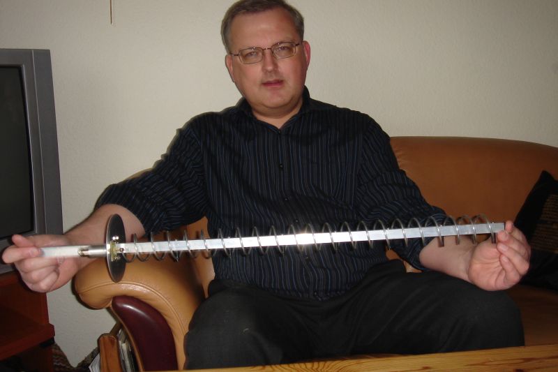 21-turns helix antenna for 13 cm
May 2009 - Hustler 4BTV performance
You can't judge an antenna by listening or transmitting
with it just a few days or evenings. You must use it for some time under
different propagation conditions to make a fair evaluation.
The first thing I noticed about my
4BTV was the noise. On 20 meters, the noise level during the day was S3.
The band was open, and many European stations were heard. Ground plane
antennas have a general problem picking up noise more easily than other
antenna types. And the vertical polarization of the ground plane is more
noise-sensitive than antennas having horizontal polarization.
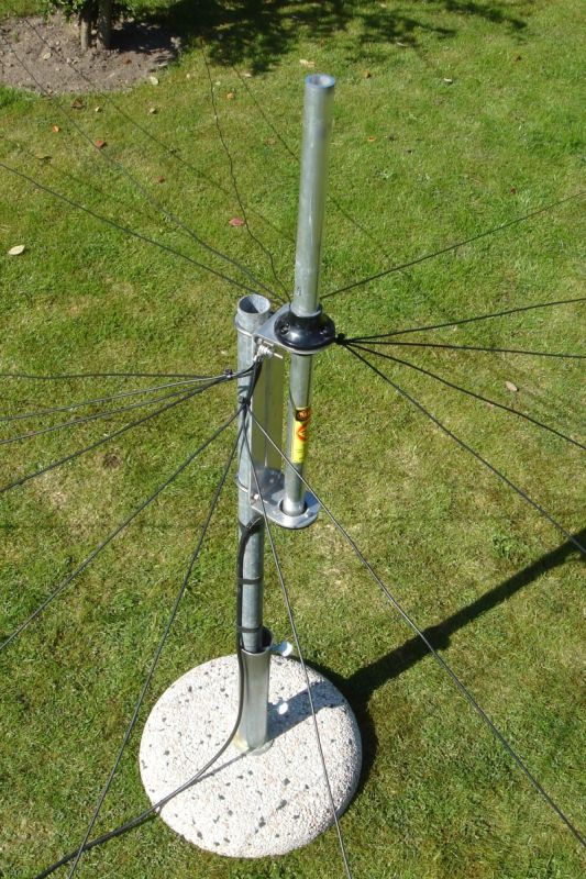 16 radials are attached to the
Hustler 4BTV
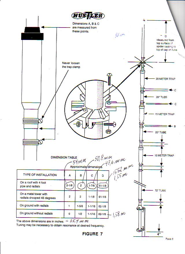
April 2009 - Tuning the Hustler 4BTV
I've attached 16 radials to my Hustler
4BTV: 4 x 8'9" (2.67 m) for 10 metes; 4 x 11'9" (3.58
m) for 15 meters; 4 x 17'6" (5.33 m) for 20 meters, and 4 x
35' (10.67 m) for the 40 meter band.
Firstly I set the spacing
between antenna elements to factory settings. This is indicated by
"Initial" in the table below, where also the final measurements can be
found.
Hustler 4BTV element spacing
Dimensions A, B, C, and D can be
seen in this figure, which
is scanned from the Hustler 4BTV "Installation
Instructions".
Secondly, my goal for the tuning process was to obtain SWR
values less than 2 on any band. The final results are shown in the
following tables. Had I desired to push SWR further down, I would have had
to adjust the radials or to adjust the traps. Neither of these options
were attractive this sunny Saturday afternoon, so I picked an antenna
tuner from the closet and put it between the transceiver and the antenna.
SWR on 10 meters
SWR on 10 meters is just fine. A tuner is not needed
on this band.
SWR on 15 meters
The SWR on 15 meters is poor. Acceptable SWR
figures are only found in the CW portion of the band.
SWR on 20 meters
SWR on 20 meters is not satisfactory. A tuner
should be used.
SWR on 40 meters
The SWR on 40 meters is
OK - a tuner is not necessary here.
February - March 2009 The antenna project is currently put on
hold. January 2009 -
More antenna preparations
The coax cable at the antenna
end needs protection against rain and moisture. I used
electrical tape and many brushstrokes of black Plastidip which
is a multi-purpose rubber coating. I purchased a .429
liter can from a danish yachtshop.You can view the
result in the picture below. 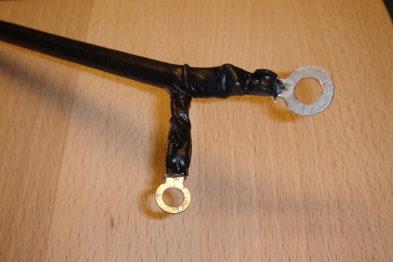 The coax cable is protected with
Plastidip.
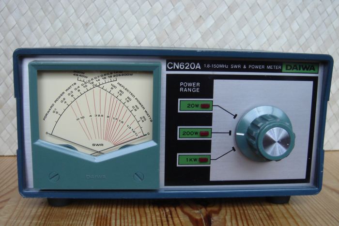
Another preparation task was
repairing my SWR meter. I bought a used Daiwa CN620A
cross needle meter some
time ago. But it did not measure accurately as a 50
ohm dummyload connected to the antenna side showed SWR = 1.3. So
I had to do some troubleshooting. It
appeared that the 2 ceramic
trimming capacitors within the sensor unit were broken due to age.
The meter accuracy was restored after having
replaced them.
December 2008 - Assembling my new
antenna
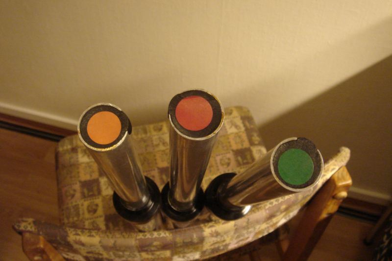 The 4BTV traps are color coded.
Assembling my new Hustler 4BTV
antenna went smoother than expected. The factory provided written
instuctions were easy to follow and contained many figures. The 3 traps are color coded:
the 10 meter trap is orange, the 15 meter trap is red,
and the 20 meter trap is green. Nice
touch, Hustler!
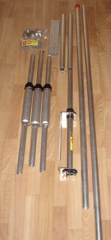 Hustler 4BTV ready for
assembly.
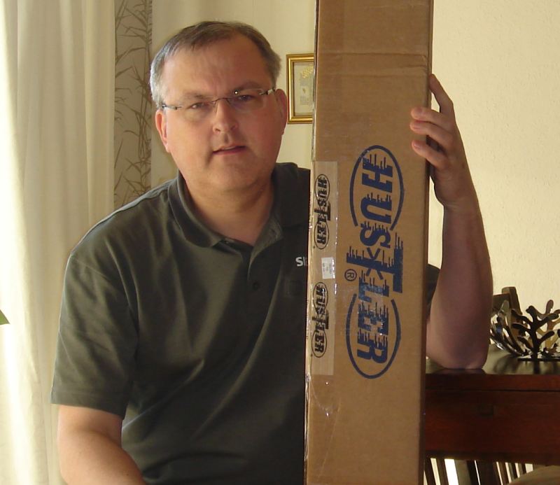
November 2008 - I need a DX
antenna!
After some investigation and
searching through eham.net reviews, I have decided to buy the Hustler 4BTV
ground plane antenna. It
covers 10-15-20-40 meters and provides low angle radiation, which is needed for making DX contacts.
The Hustler antenna will be
mounted on the flat roof of my carport and 12 radials
will be used as the ground plane. I bought the radials pre-cut
from DX-Engineering
, the same company that sold me the 4BTV.
Delivery was fast, as I placed
the order and received the goods within the same week. If you
live in Europe and plan to do
the same, you should know that shipping via air from USA to Denmark is quite expensive!
|
|||||||||||||||||||||||||||||||||||||||||||||||||||||||||||||||||||
|
You are welcome to visit my homepage
A Tiny QRP Page by OZ1BXM. Have your say on this blog: Send me a mail! This blog is listed at Ham Radio Blogs and at The DX Zone: 
|

