Sequencer
An updated version is described here: Sequencer with variable delay
This page describes my homemade sequencer. It controls the different components of my EME station.
Function
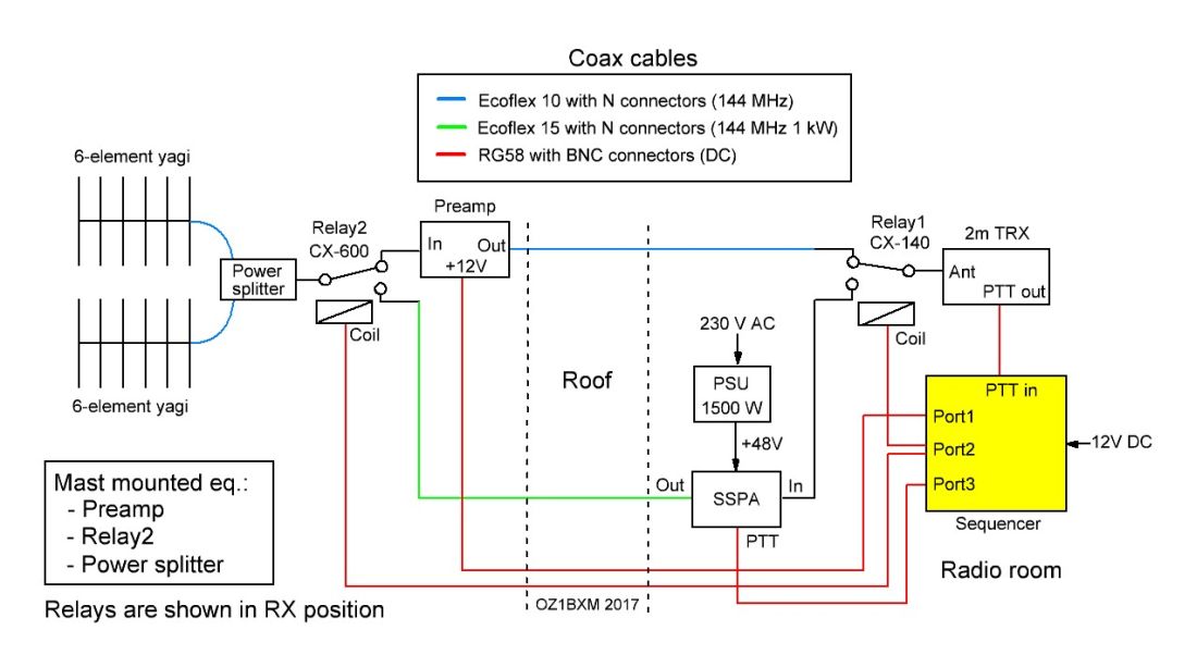
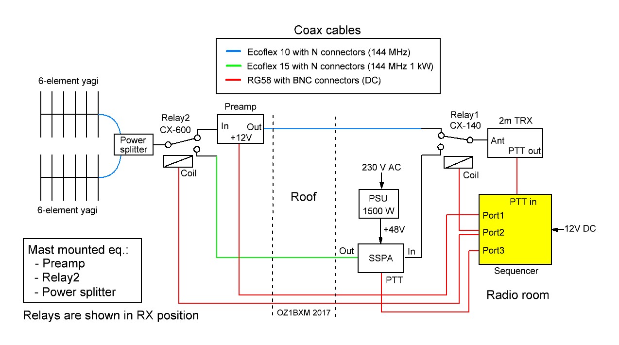
Fig. 1. The sequencer (yellow block) controls my EME station.
The sequencer is highlighted in yellow on figure 1. Three events must take place
in a specific order when PTT is activated and the system switches
from RX to TX.
- Disable the preamp (remove 12V from port 1)
- Change relay1 and relay2 from RX to TX (port 2)
- Enable the SSPA (port 3)
When PTT is deactivated, the system switches from TX to RX. The events are now executed in reverse order.
- Disable the SSPA (port 3)
- Change relay1 and relay2 from TX to RX (port 2)
- Enable the preamp (apply 12V to port 1)
Circuit Diagram
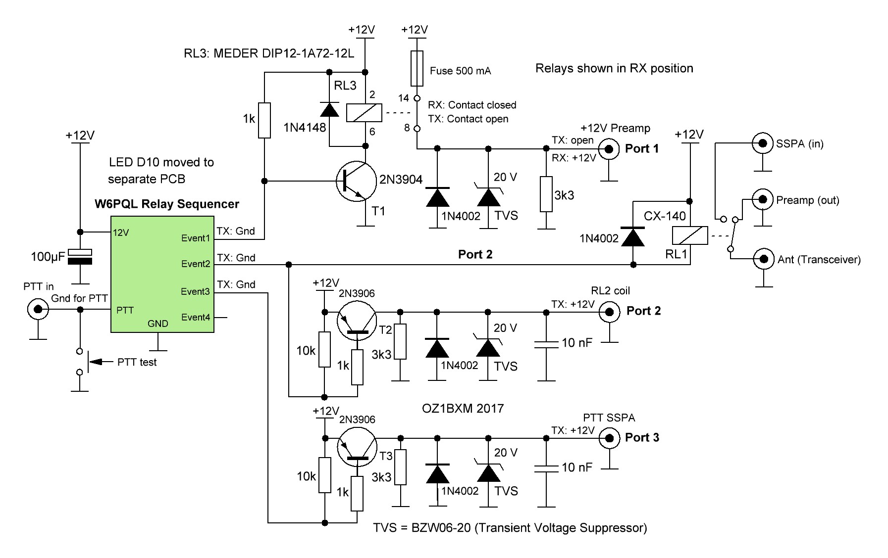
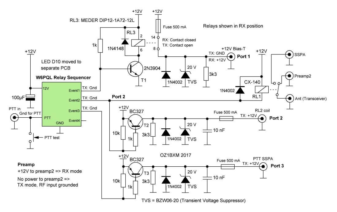 Fig. 2. Circuit Diagram.
When +12V DC is applied to preamp2 via the bias-T, the preamp is in RX mode . When 12 V is removed during TX, a relay in preamp2 will ground the input and protect the electronic circuit.
The
heart of the sequencer is the Relay Sequencer,
which is a kit
developed and sold by W6PQL. I have modified the circuit to get 100 ms
between each event. I've added overvoltage
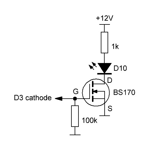
protection on port1 - port3. It was necessary to move the LED
D10 (on the W6PQL PCB) to a small Veroboard because D10 was constantly on
during RX (caused by a low voltage at the base of T1).
Fig. 3. This circuit controls D10.
The "W6PQL Relay Sequencer" has an unused 4th output (Event4). This output can be used for enabling a transceiver.
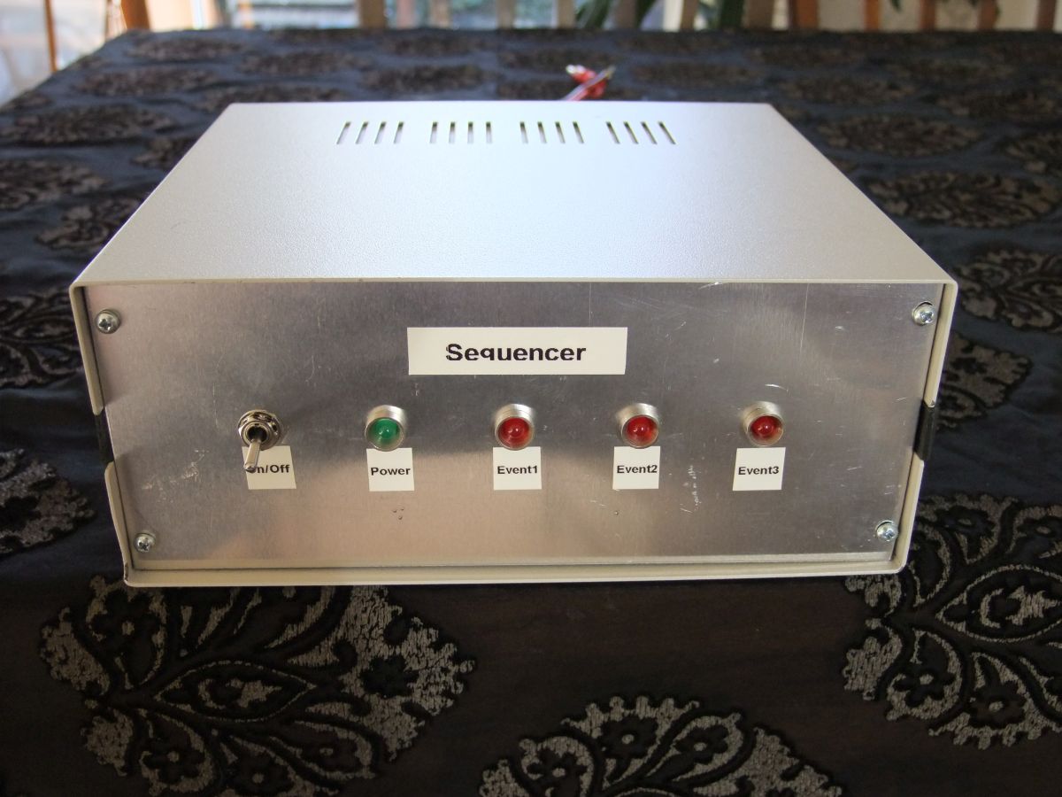
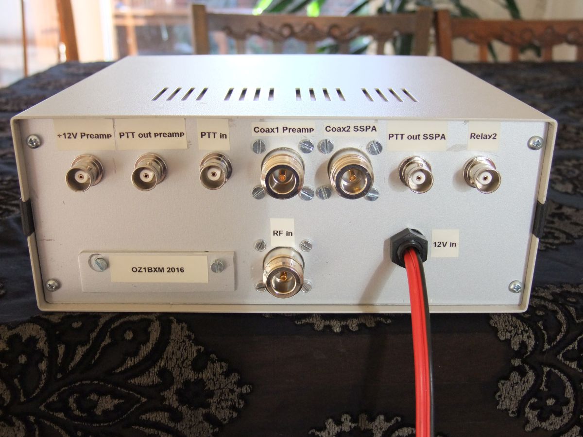
Fig. 4. Front view. Click to enlarge. Fig. 5. Rear view. Click to enlarge.
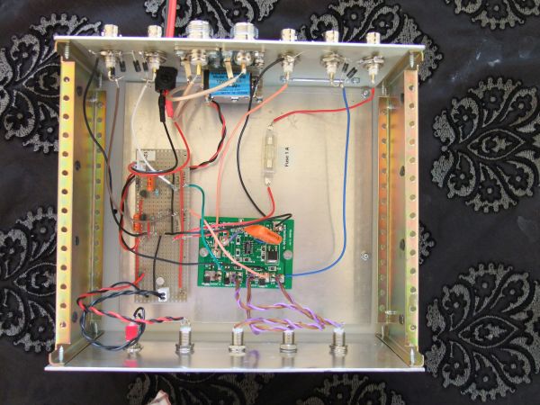
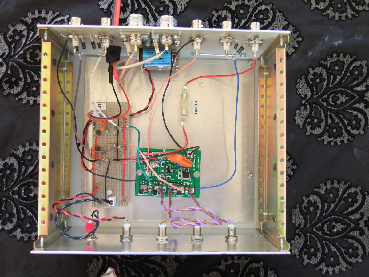
Fig. 6. Inside the sequencer. Click to enlarge.

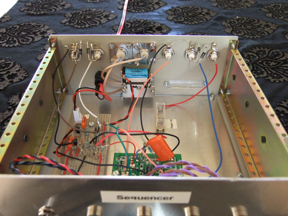
Fig. 7. Another view inside the sequencer. Click to enlarge.
Latest development
I've
added current monitoring of Preamp2 and RL2. I've also expanded the
sequencer to support two different types of preamp:
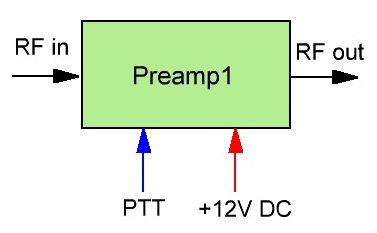
Fig. 8. Preamp1. | The preamp in fig. 8 requires a constant power supply.
RX/TX switching is done by activating/deactivating the PTT line.
Preamp1 requires three cables from mast to shack:
|
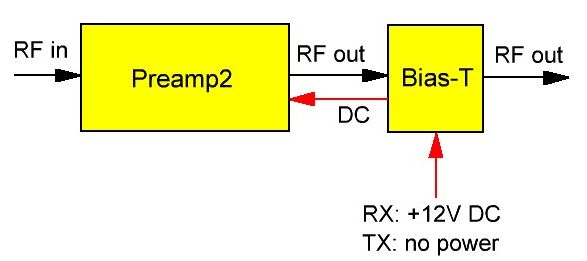
Fig. 9. Preamp2. | The preamp in fig. 9 is powered via the coax cable.
RX/TX switching is done by switching the DC power on/off.
Function of the bias-T:
It injects DC into the coax cable in the direction of the preamp. The
coax connected to the transceiver does not carry DC. The RF
signal is not affected by the DC.
Preamp2 requires only one cable from mast to shack:
- Coax cable (carries RF and DC)
The circuit diagram in fig. 2 supports Preamp2. Extra-2 (HA8ET) works just like Preamp2. I use this premap for EME on the 2 meter band. |
The latest circuit diagram shows how both Preamp1 and Preamp2 are supported, and how current monitoring works.
Written by OZ1BXM Lars Petersen. Latest revision: 10-Sept-2017.
Home