Sequencer with variable delay
This page describes my homemade sequencer. It controls the different components in my EME station.
Function
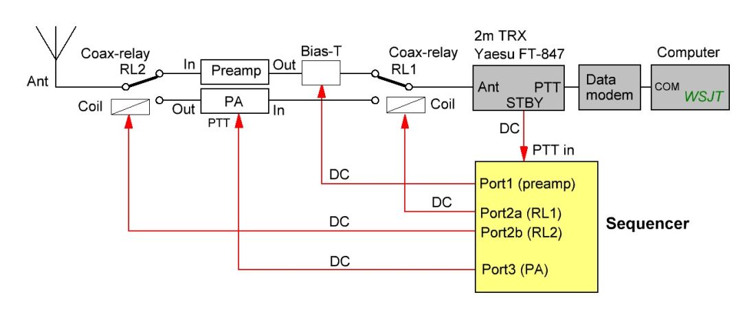
Fig. 1. The sequencer (yellow block) controls my 2 meter EME station.
Figure 1 shows how the sequencer controls the hardware. Three events must take place
in specific order when PTT is activated and the system switches
from RX to TX.
- Disable the preamp (remove 12V from port 1)
- Change RL1 and RL2 from RX to TX (port 2a/2b)
- Enable the PA (port 3)
When PTT is deactivated, the system switches from TX to RX. The events are now executed in reverse order.
- Disable the PA (port 3)
- Change RL1 and RL2 from TX to RX (port 2a/2b)
- Enable the preamp (apply 12V to port 1)
Figure
1: When WSJT commands the transceiver to change from RX to TX,
it activates the transceiver's PTT line. The STBY port follows the
PTT line immediately. WSJT will delay the audio 200 ms (defalut
value). This delay can be configured in WSJT (Settings >
Advanced > TX delay). I've set TX delay to 300 ms.
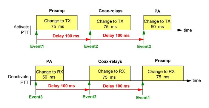
Fig. 2. Events and delay.
Figure 2 above shows how Event1 must finish before Event2 begins, and so on. The
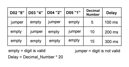
100 ms delay in figur 2 may not be optimal for
everyone. If 200 ms delay is required, the
user fits jumpers for 10 decimal and then resets the Arduino Nano.
The delay is now 200 ms.
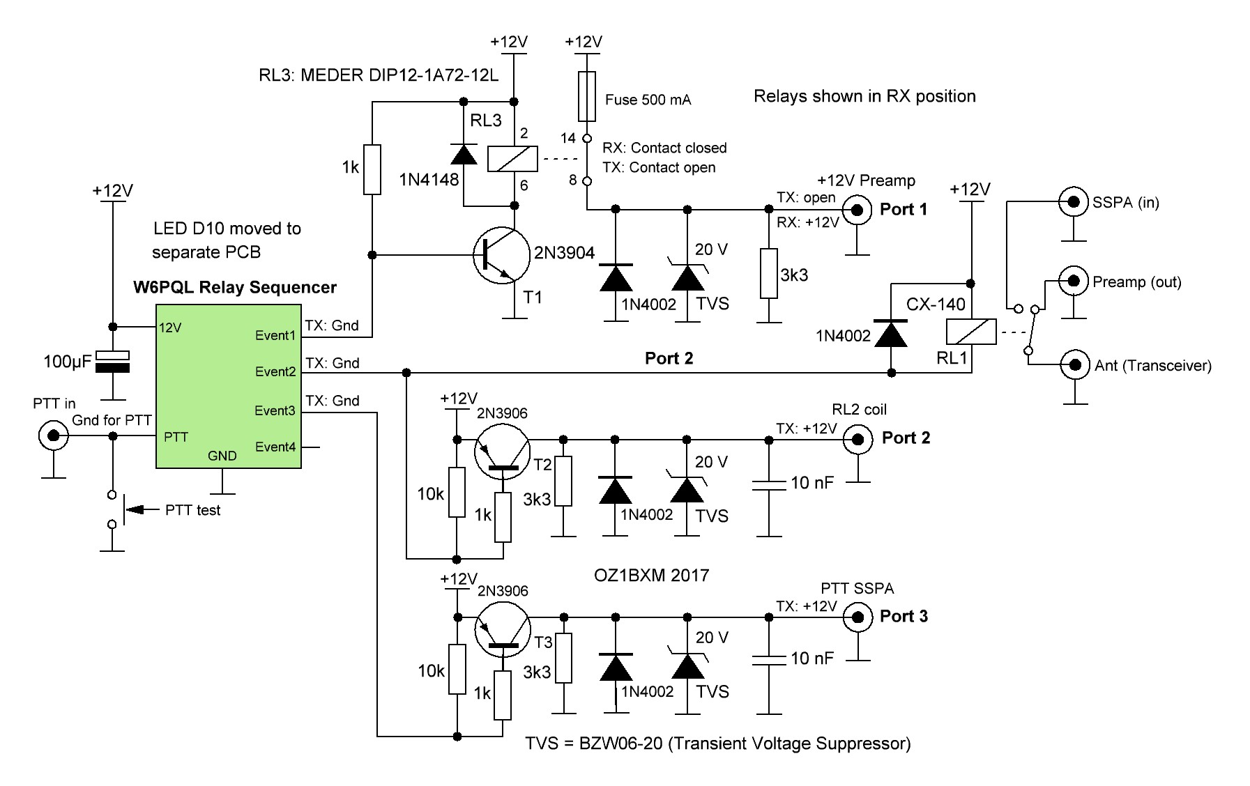
Circuit Diagram
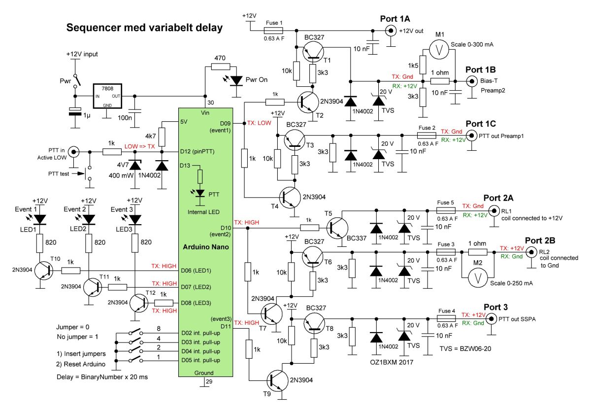 Fig. 3. Circuit Diagram.
The
heart of the sequencer is the Arduino Nano. Three digital
pins (D06-D08) are used for controlling the LEDs on the front
panel, and D09-D11 are controlling the output ports.
The pins D02-D05 are used for setting a binary number
which decides the delay in milliseconds. The delay range is from 20 ms
to 300 ms in steps of 20.
Fig. 4. Delay is set using jumpers.
Panel meters M1 and M2 monitor the current flowing through Port1B and Port2B. Both
ports supply power to equipment mounted in the antenna
mast (preamp, RL2). I like to keep an eye on their power
drain. Each unit use about 150 mA when active.
Hardware
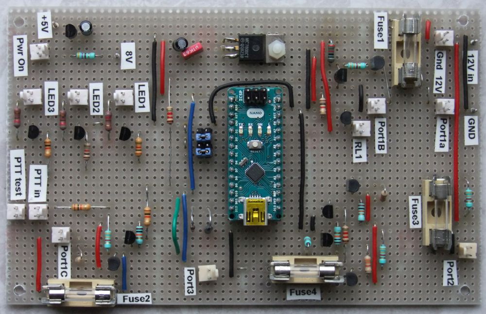
Most
discrete components are fitted on a Veroborad (stripboard). Some
components are soldered directly onto the BNC-sockets on the rear
panel.
Fig. 5. The populated PCB.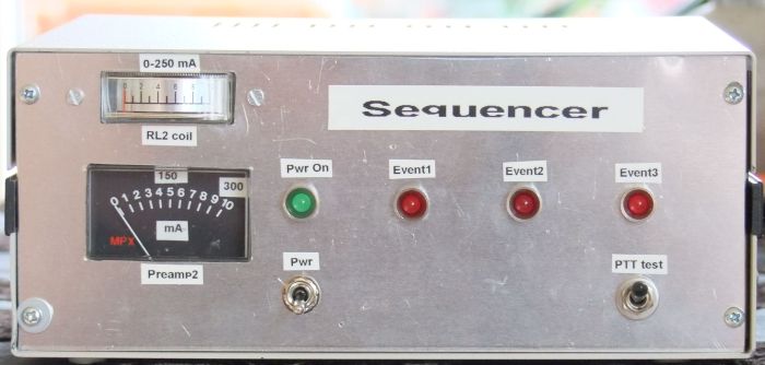 Fig. 6. Front view.
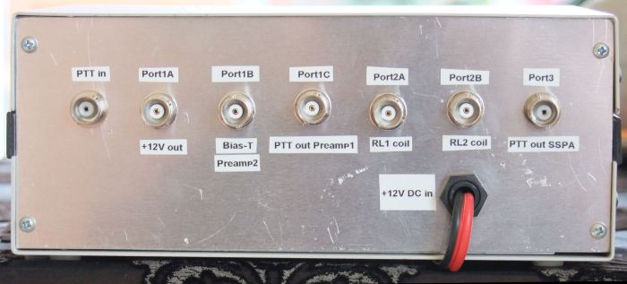
Fig. 7. Rear view.
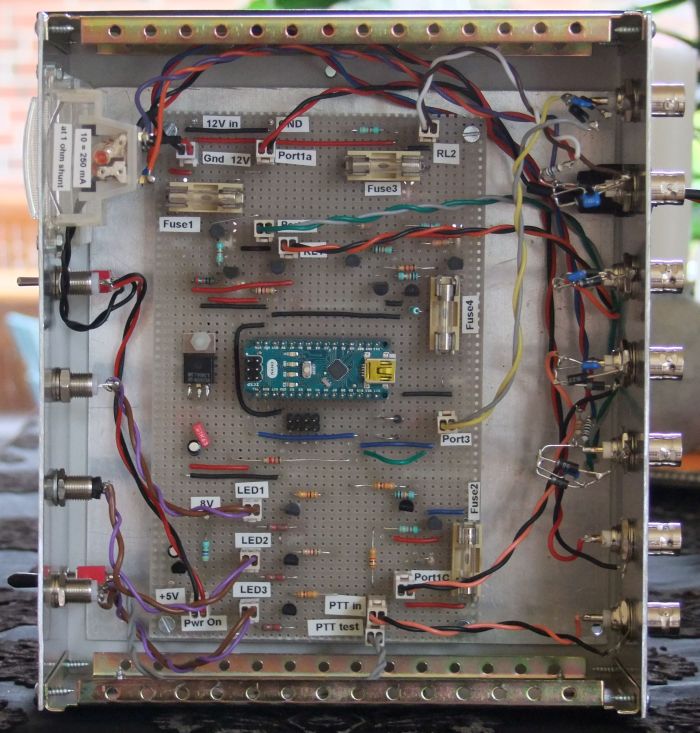
Fig. 8. View inside the sequencer. Software
The
software is an Arduino sketch (sketch = a file containing source code).
The sketch is imported into Arduino IDE, compiled, and uploaded
to Arduino Nano via the USB-port.
This file contains the sketch for the project: sequencer_oz1bxm.zip
Written by OZ1BXM Lars Petersen 17-Oct-2017. Revised 15-May-2019.
Home