QO-100 Satellite Station
Amateur radio communication via a geostationary satellite
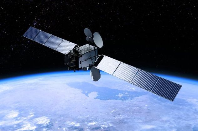 | General info Official satellite name: Es'hail-2. The radio amateurs (AMSAT) designated it Qatar Oscar 100 (QO-100). Satellite built by Mitsubishi Electric Corporation. Weight: 5300 kg Launched: 15-November-2018 by SpaceX from Kennedy Space Center, Florida, USA. Amateur radio service was opened on 14-February-2019. Orbit: Geostationary. Es'hail-2 orbits 35,786 km above the Earth's surface at Equator, and it follows the Earth's rotation. The satellite appears to stand still in the sky. My uplink- and downlink antennas are pointed towards the satellite, and they are mounted permanently (no rotator). The distance from my house in Holstebro, Denmark to Es'hail-2 is 39,171 km. Transponders: NarrowBand (500 kHz bandwidth), and WideBand (8 MHz bandwidth). Web-SDR for NB transponder: https://eshail.batc.org.uk/nb/ Web-SDR for WB transponder: https://eshail.batc.org.uk/wb/ More info: https://amsat-dl.org/eshail-2-amsat-phase-4-a |
10 GHz downlink: | |
 Receive chain for QO-100. | Receive chain The signal from the satellite's narrowband transponder is received on 10.489 GHz. This signal is mixed with the local oscillator (9.75 GHz) in the LNB, and the IF frequency is 739 MHz. The IF is forwarded to the SDR dongle where it is decoded and displayed. The Bias-T supplies power to the LNB while being transparent to RF. |
|
Triax offset dish with LNB. |
Satellite dish LNB Improved LNB Cable |
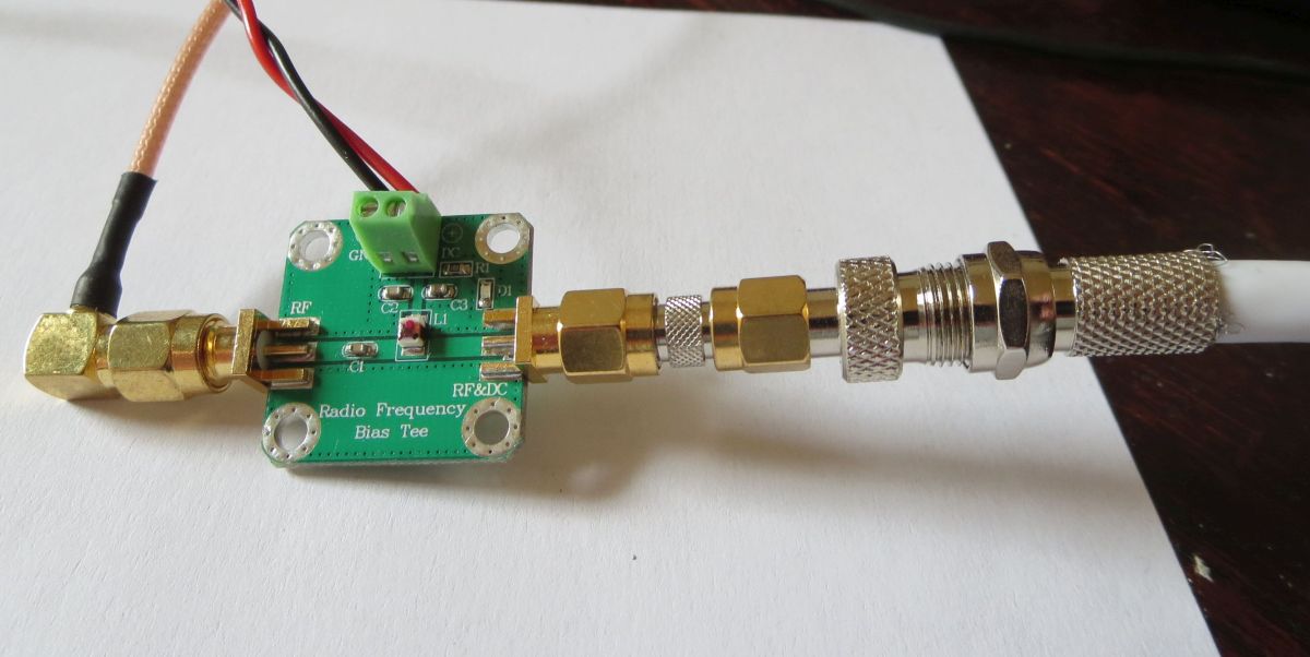 Bias-T. | Bias-T I found the Bias-T on ebay.com. It supplies 12 V 100 mA to the LNB via the coax cable, and keeps 12 V away from the SDR. |
 SDR dongle. | SDR The receiver is an SDR dongle from rtl-sdr.com. It is tuned to 739 MHz (NB transponder). The SDR software on the computer is SDR sharp (SDR#). |
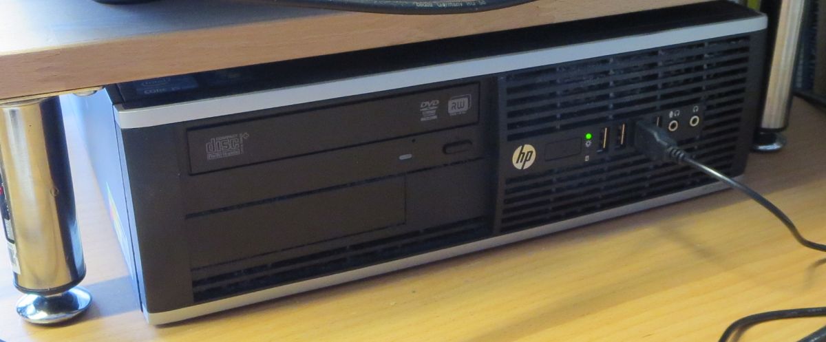 Desktop PC. | Computer Desktop PC running Windows 10 (64 bit). CPU is Quad-core i5-2400 at 3.1 GHz. RAM is 4 Gb. |

2.4 GHz uplink:
|
Transmit chain for QO-100. |
Transmit chain Yaesu FT-847 puts out 3 W on 432 MHz. The transverter converts the signal to 2400 MHz at 2 W. The attenuator reduces the signal with 6 dB not to overload the PA. The PA amplifies the signal to 20 W PEP, which is sufficient for all modes including SSB. The signal is radiated towards the satellite by a helix antenna (RHCP). If only the transverter is used (no PA), the output power at 2400 MHz will be 2 W. This power level can be used for CW and digimode. |
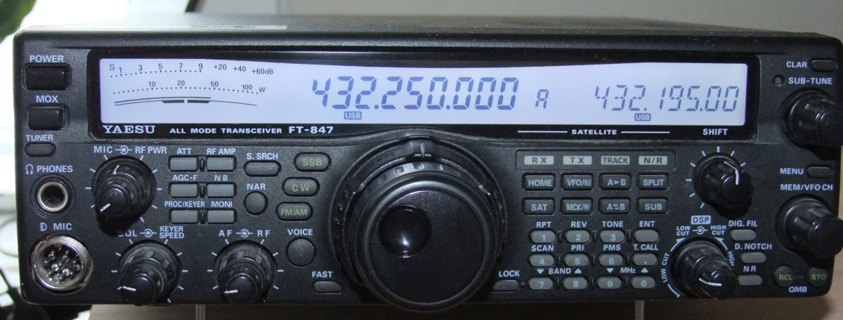 Yaesu FT-847 transceiver. | Transceiver My VHF/UHF transceiver Yaesu FT-847 is used for transmitting on 432 MHz. The PSU is a Kenwood PS-30. |
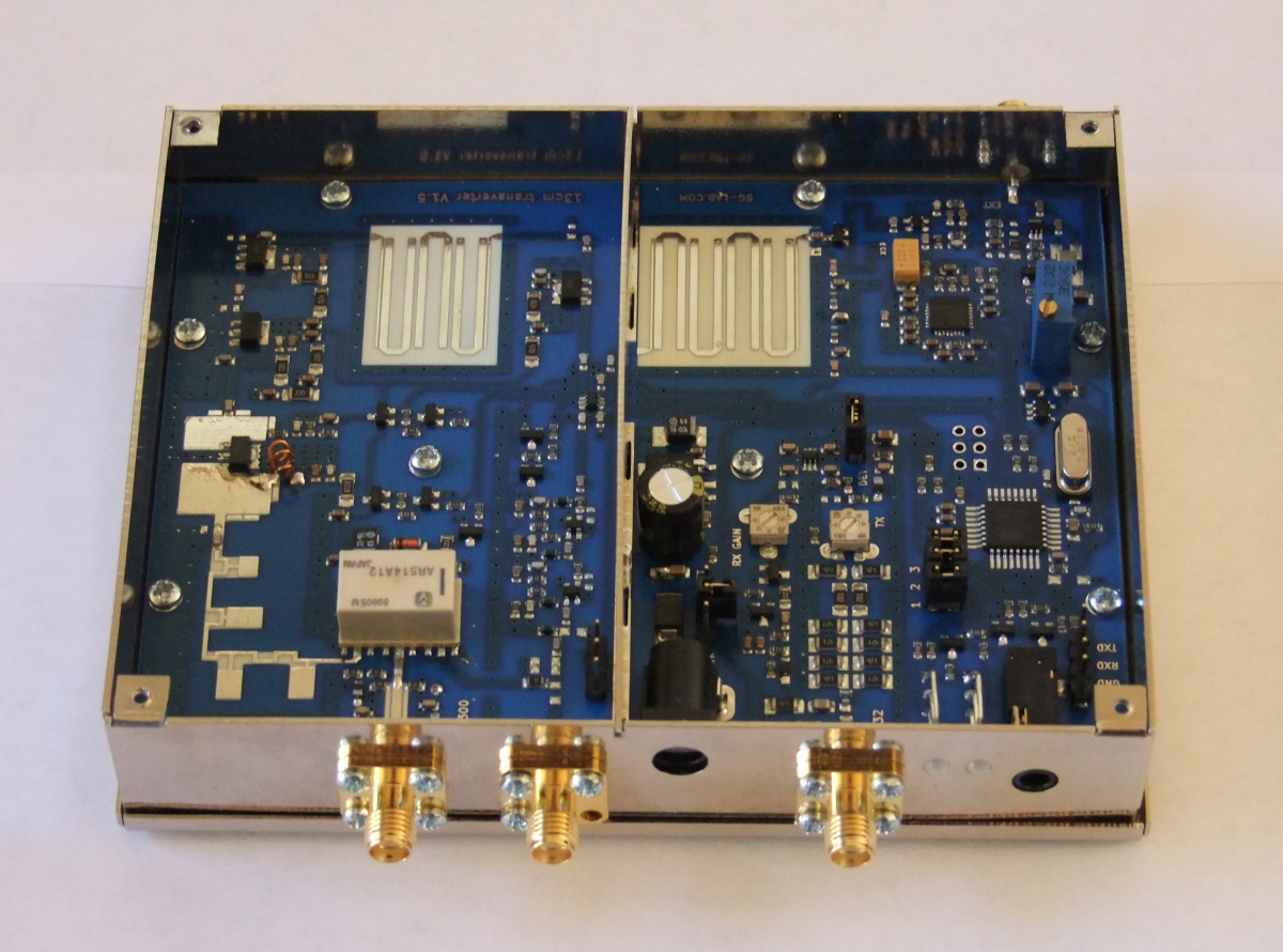 13 cm transverter. |
13 cm transverter I choose this transverter because:
|
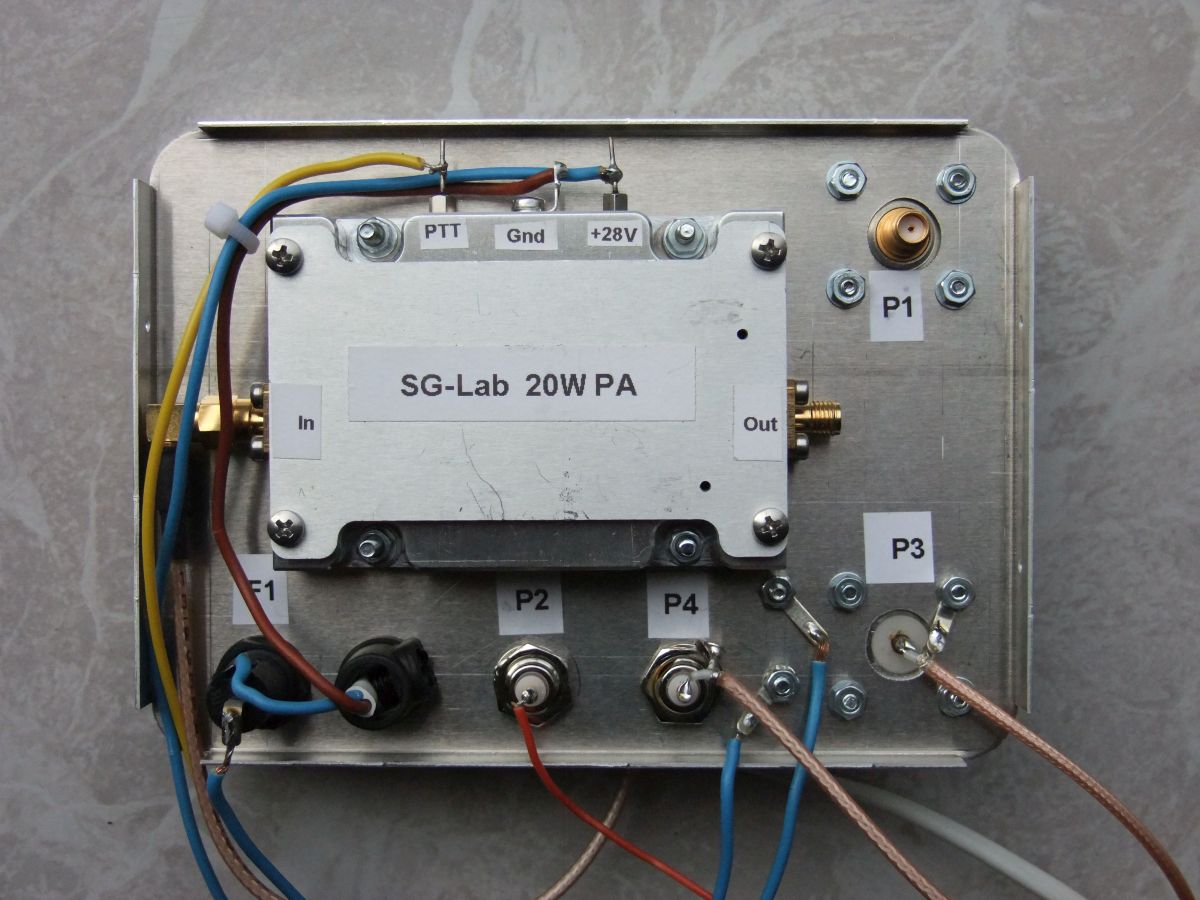 13 cm PA. | 13 cm PA I choose this PA because:
|
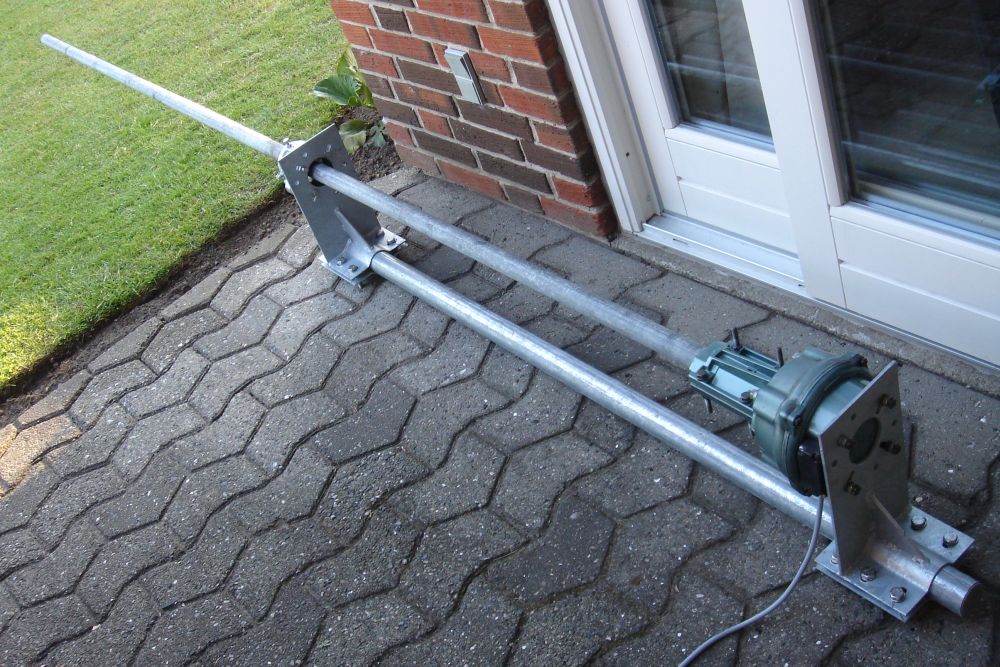
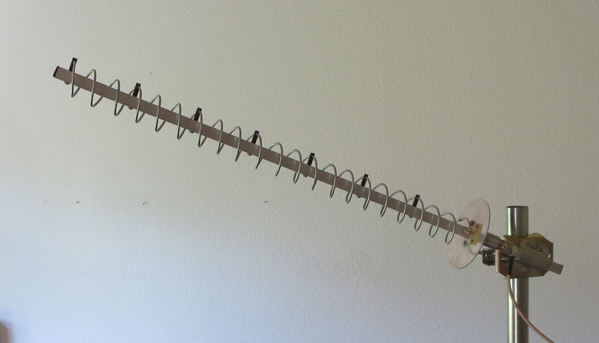 13 cm helix antenna. | 13 cm antenna I'm using a 21-turns helix antenna for the uplink. The product name is Helix-13 and I purchased it 10 years ago at wimo.com. The antenna gain is about 14 dB. Wave polarization is RHCP (Right Hand Circular Polarization). The antenna is pointed directly at the satellite in the sky. |
 The 13 cm upconverter (click to enlarge). | Upconverter diagram The circuit diagram of the upconverter is shown to the left. The upconverter is built into a metal box. M1 measures DC voltage and DC current. Based on the consumed current, one can estimate the RF output. IC1 converts 28 V DC to 12 V DC. LED1 is on: 28 V is present. LED2 is on: PTT is active. The PTT line is controlled by the transceiver. |
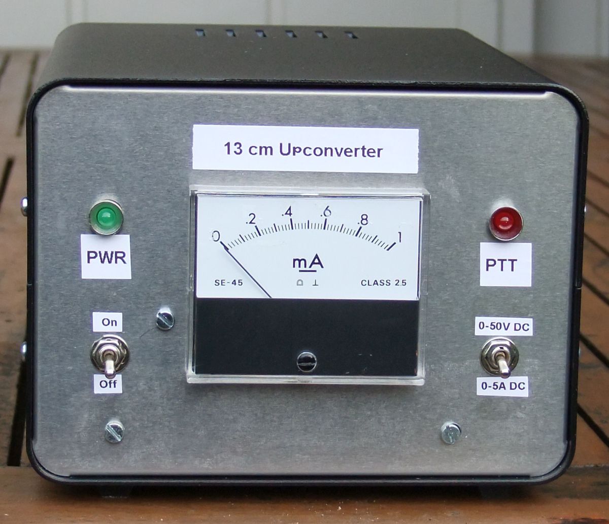 13 cm upconverter - front view. | Upconverter, picture 1 |
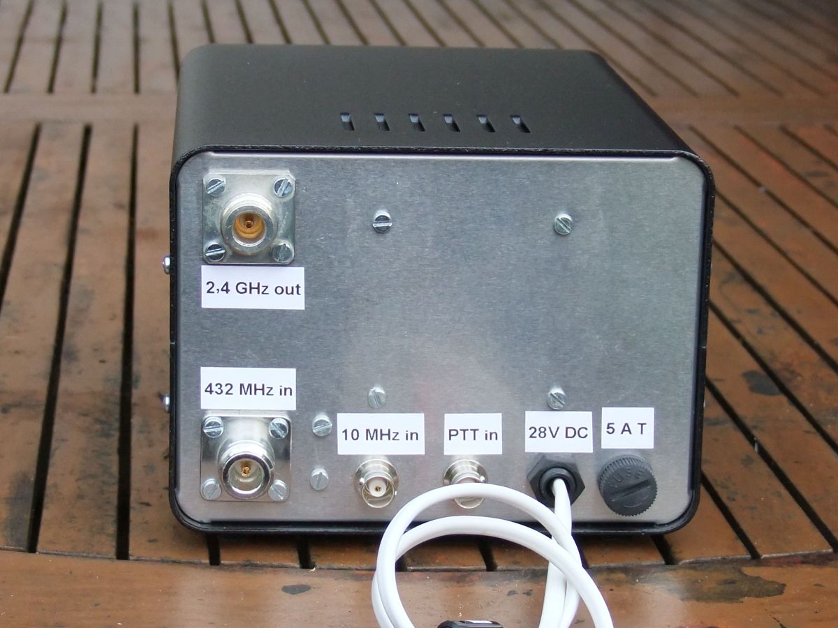 13 cm upconverter - rear view. | Upconverter, picture 2 |

Written by OZ1BXM
Lars Petersen 24-April-2019. Revised 02-Jan-2021.