|
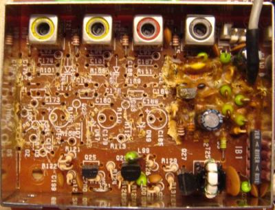
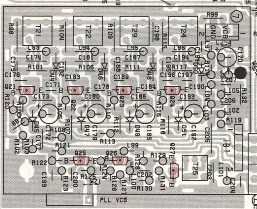
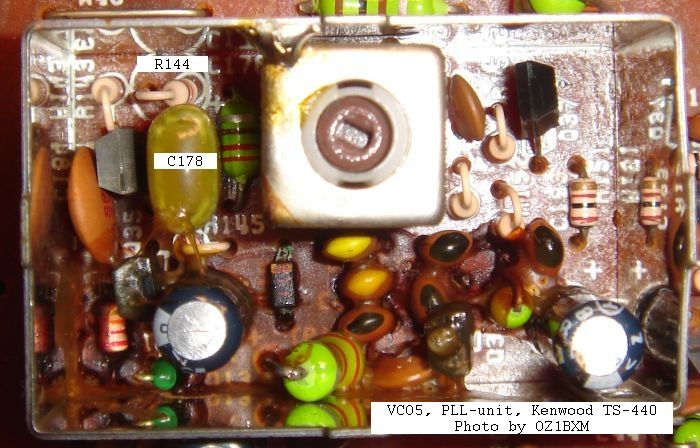
Fig. 2. Glue halfway removed.
|
Removing the conductive glue
Make notes on how cables etc. are connected to the RF-unit, or take a
close-up picture. Now disconnect the cables, remove the screws, and
extract the RF-unit. The glue is removed using hand tools. Use a stanley knife for cutting out pieces of glue and for cleaning
(scraping) the component side of the circuit
board. A screwdriver is handy for lifting components when unsoldering. A long-nosed plier
is used for removing components and pieces of goop. This work
requires several hours of intensive labour. I recommend you take regular breaks!
Some people say that components dirty with glue can be
removed, cleaned, and reused. I could not do that. The glue removal
proces will probably destroy many components. It is easier to
clean the circuit board when everything on it is removed.
Do not destroy the 2SC2668(Y) transistors.
Unsolder them, clean them carefully, and reuse them. I offer
this advice because it was difficult for me to obtain new transistors.
I've later discovered, that 2SC2668(Y) is available on Ebay. |
 | Alternative method of removing the glue Update
September 2021. VK5NNT Neville describes his method of
removing the glue: "What I have discovered
is that I put pure eucalyptus oil on the glue and it softened it to a
jelly condition. I used a small plastic syringe to put drops of
eucalyptus oil on the glue. It acts fairly quickly and does not require
a lot of oil; just put some on an area and test to see how long it
takes to soften. I was then able to remove the glue easily with a
paper
cutting scalpel and tweezers and used a small suction nozzle connected
to my vacuum cleaner and suck up the jellied glue. I did not remove the
components". I have not tried this method, but I would encourage
using it. Removing the glue and not the components will
greatly simplify the repair work and speed up the task! When the glue has been removed from VCO1, go to "VCO1 Adjustment" and follow the description. When the glue has been removed from VCO5, go to "VCO5 Adjustment" and follow the description. |
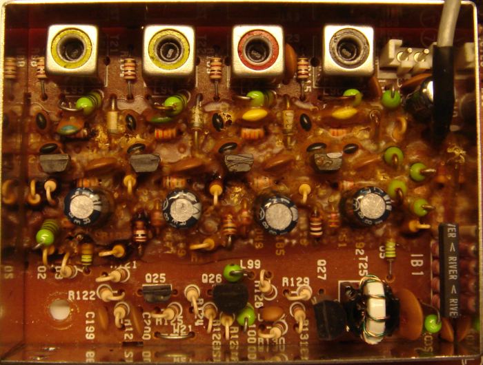
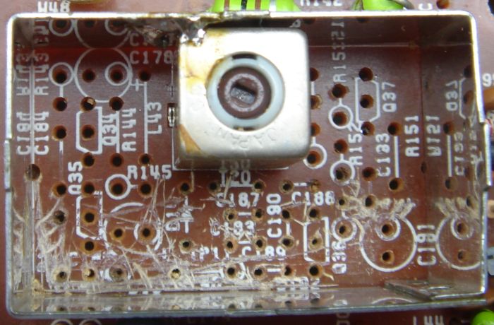
|
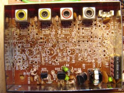
Fig. 3. VCO 1 fully cleaned.
|
Rebuilding VCO1
I ordered new components from East Coast
Transistor in New
York, USA. The
rebuild work should be divided into steps. Build one VCO and test it. Then continue with the next
one. The
original varicap ITT310TE (D44, D46, D48, D50) can be substituted by
BB139. The original switching diode MA858 (D45, D47, D49, D51) can be substituted by BA244. For C175, C182, C188, and C195 the factory
value of 5 pF may be too low. A low value can make the oscillator stop. Increasing the value may be
necessary to keep the VCO running. Here are the values from my rebuild of transceiver-2 (varicaps were BB139): | Q21 (67 - 75 MHz) | Q22 (59.5 - 67 MHz) | Q23 (52.5 - 59.5 MHz) | Q24 (45 - 52.5 MHz) | C174 = 33 pF
C175 = 6.8 pF | C182 = (5 + 2.2) pF | C187 = 47 pF
C188 = 10 pF | C194 = 82 pF
C195 = 10 pF |
WB7DFV Dave used NTE614 as
varicap replacement. He wrote: "It turns out that the NTE614 was a good replacement. I
could not get the oscillator with T21 to work and had to reduce
the 39 pF cap to a 22 pF cap. Now the radio works perfectly."
KA5ZWY Larry told me that he had problems with T22. However, when he applied
pressure to the PCB near T22, the problem disappeared.
Resoldering T22 and surrounding components will solve that
problem.
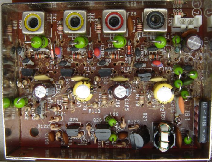
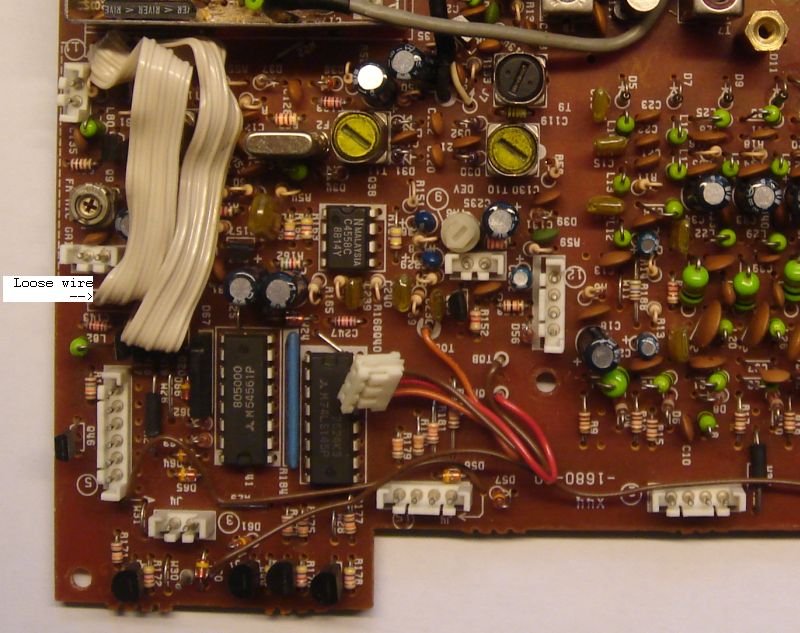
|
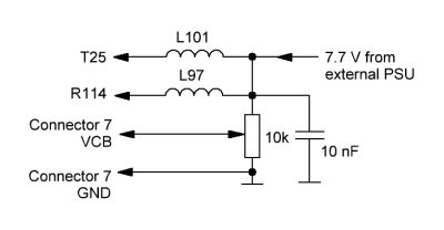
Fig. 4. Hooking up wires before testing VCO1. | Hooking up wires
It
is a good idea (but not mandatory) to test the four oscillators in
VCO1 before the
RF-board is put back in the chassis. This test requires some wiring
to emulate the voltages within the transceiver.
An external PSU supplies 7.7 V DC at 60 mA. One
end of L101 and L97 is desoldered from the PCB, and this end is
connected to 7.7 V DC. The other end feeds the circuit.
The
10 nF capacitor is important. It decouples RF from
the circuits in VCO1 and from the potmeter wires.
Once I forgot this capacitor, the active
oscillator's frequency jumped up and down! The 10 kohm potmeter creates the VCO voltage.
|
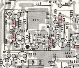
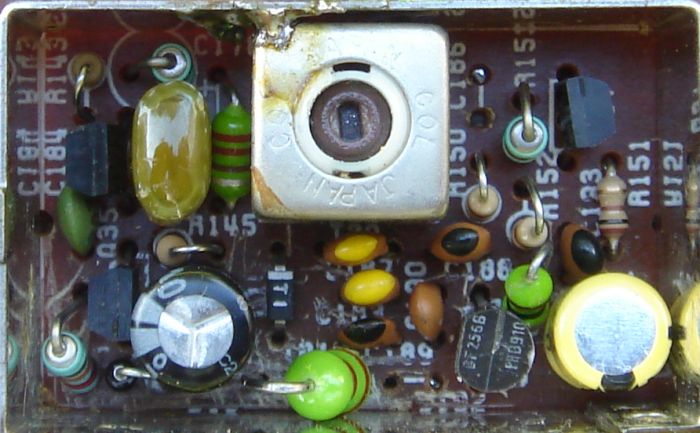
|
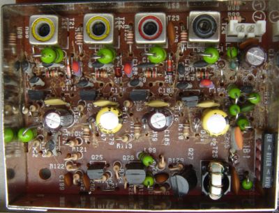
Fig. 5. VCO1 rebuild finished.
|
Testing VCO1
Figure 5 shows the rebuilt VCO1. Some of the new components are soldered on the
copper side of the PCB (C171, C178, C184, C190). There are 2 empty
holes near Q21, Q22, and Q23 where no
components are fitted.
An oscillator is
activated by applying 7.7 V to its collector via the
100 ohm
resistor (R102, R107, R112, or R118). One side of the resistor (the side connected to
Q17-Q20) is desoldered from the PCB, and 7.7 V is applied to this end.
The voltage range for testing each VCO should be 2.0 V to 6 V.
The reason for testing at 2.0 V is that this is the
default control voltage. If the VCO cannot oscillate at
2.0 V, the PLL unlocks causing dots-in-display.
When the
PLL is locked, the VCO voltage should be within the range 2.5 - 6
V. A good connection point for
a frequency counter is "PLL VCO" which is at the edge of the PCB. I
added a 22 pF
capacitor between "PLL VCO" and the counter. The frequency range of each oscillator is printed in the circuit diagram. |
|
VCO1 adjustment
Mount the RF-unit and reconnect all cables. Follow the Service
Manual p. 92 item 13. Please note the typo at 3rd step. The
correct value is 14.4999 MHz, not 14.9999 MHz.
| Main dial | TP10
(Transceiver-1) | TP10
(Transceiver-2) | Remarks
| | 29.9999 MHz | 2.49 V | 2.47 V | Adjust T21 to get this reading | | 22.0000 MHz | 5.94 V | 6.06 V | | | 21.9999 MHz | 2.51 V | 2.45 V
| Adjust T22 to get this reading | | 14.5000 MHz | 5.86 V | 5.94 V | | | 14.4999 MHz | 2.50 V | 2.48 V
| Adjust T23 to get this reading | | 7.5000 MHz | 5.93 V | 6.21 V | | | 7.4999 MHz | 2.38 V | 2.49 V
| Adjust T24 to get this reading | | 30 kHz | 6.62 V | 6.13 V | |
TP10 is the top of R138 (PLL-unit) and it can be accessed from the side.
|


