LEO Satellite Station and Antennas
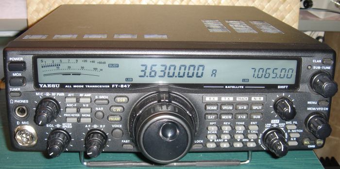 Yaesu FT-847 VHF/UHF transceiver. | Transceiver for 2m and 70 cm |
Antennas | |
|
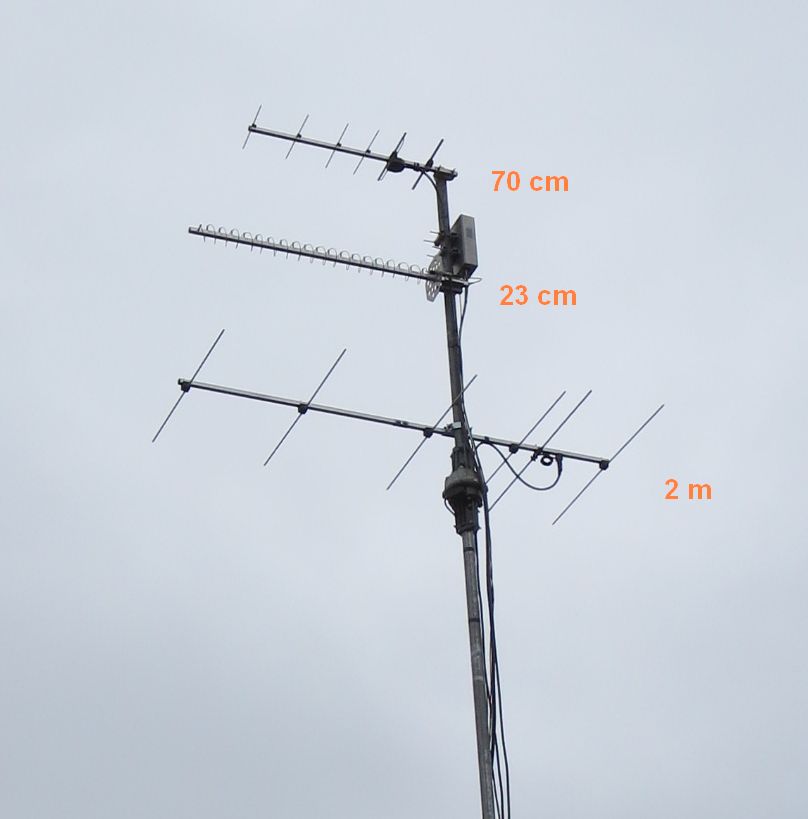
Antennas for 70 cm, 23 cm, and 2 m. |
70 cm yagi |
Equipment for 23 cm
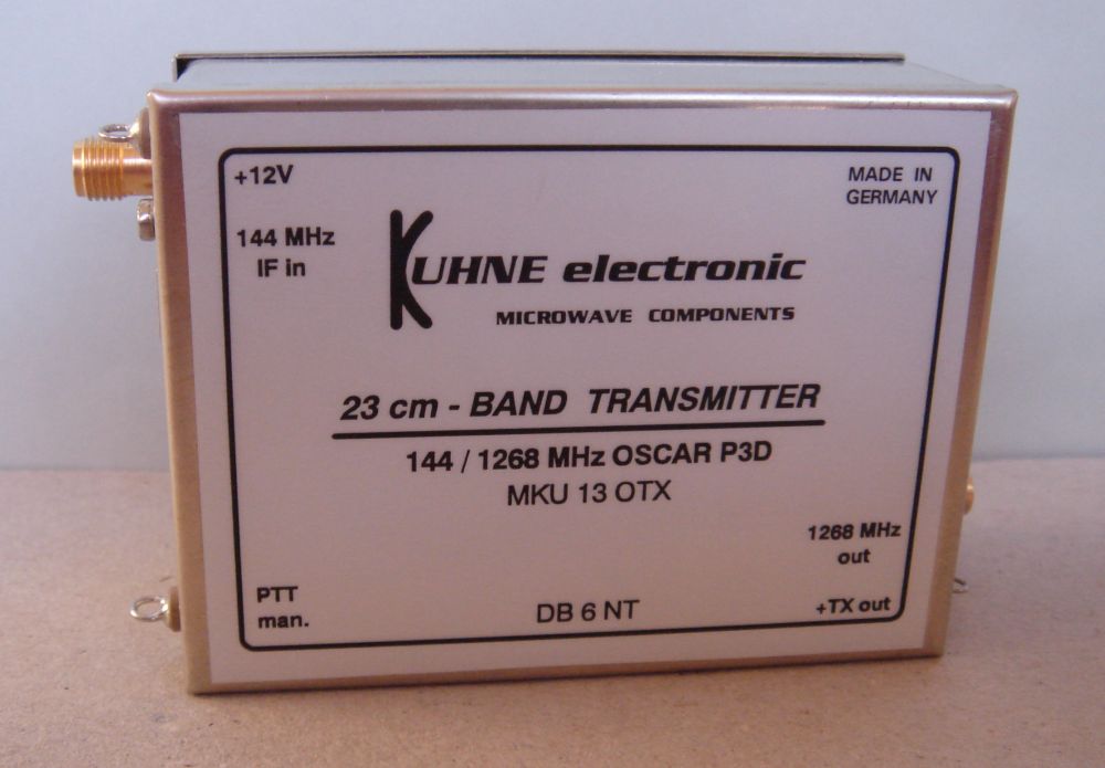 23 cm transmit converter. | 23 cm transmit converter My 23 cm transmitter is the MKU 13 OTX up-converter from Kuhne Electronic.The power level at 1268 MHz is about 1 W.The MKU 13 OTX is keyed by applying 12 V DC to the 144 MHz port via the coax cable. Keying can also be done manually (PTT man. is grounded). When MKU 13 OTX is keyed, the terminal +TX out goes high and activates the PA. You can find the circuit diagram here. |
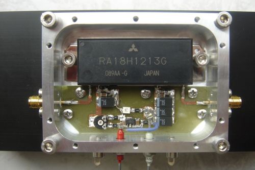 23 cm PA module. | 23 cm PA with 20 W output The active element in my 23 cm PA is Mitsubishi RA18H1213G, which is a power-module for 1240 - 1300 MHz. The PA is a kit purchased from PE1RKI Bert Modderman. The construction is described in details here. |
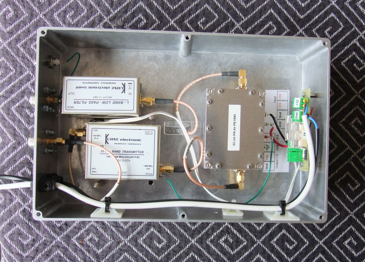 Cabinet for 23 cm TX modules. | Cabinet for 23 cm modules The cabinet contains the transmit converter, the PA, and the low-pass filter. There is also a DC distribution board. The cabinet is a diecast aluminium box from Hammond (item 1550J). The surface of the box is about 1000 cm2 which is sufficient for keeping the PA temperature low. The weatherproved box is mounted in the antenna mast. |
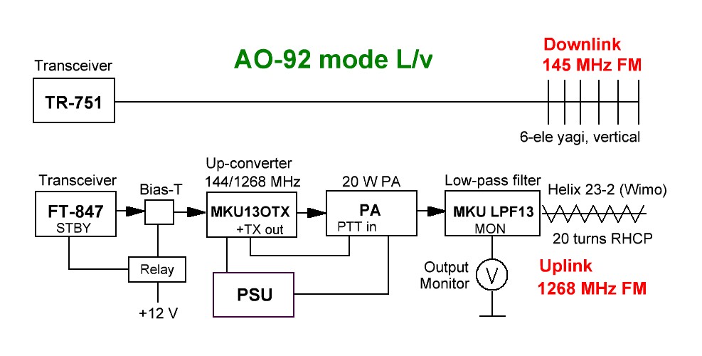 Mode L/v configuration. | Mode L/v configuration The diagram to the left shows the configuration for the satellite AO-92. Uplink is 1267.350 MHz FM, and downlink is 145.880 MHz FM. The uplink antenna employs circular polarization (RHCP) and secures a constant signal to the satellite. The downlink antenna has linear polarization. Click the picture to enlarge. |
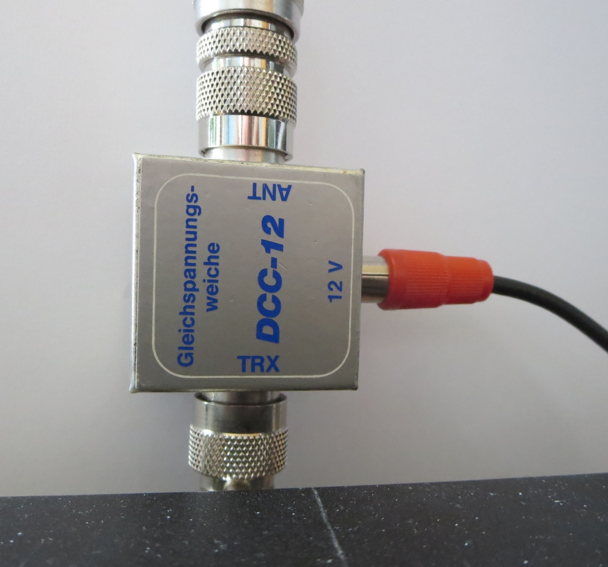 Bias-T. | Bias-T ANT: When transmitting, the bias-T injects +12 V into the coax-cable via this port. The DC voltage makes MKU13 OTX transmit. No DC voltage is applied to ANT when receiving. The port transfers RF from transceiver to antenna, both when receiving and transmitting. TRX: This port does not carry any DC voltage, only RF. The transceiver's antenna socket is connected here. 12 V: A relay (not in the photo) sends +12 V to this port during transmit. No voltage is applied when receiving. The relay's circuit diagram is here (opens in a new tab). |
Antenna rotator system
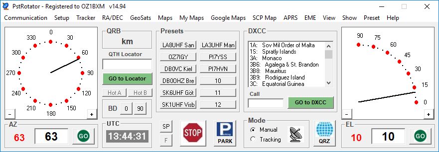 | Tracking software The tracking software is PstRotator which runs on my PC (Windows 10 Home 64 bit). The current position of each rotator is displayed. The satellite software (SDR Console) generates position data and forwards them to PSTRotator. Position data are then processed and forwarded to the ERC-3D controller via an RS-232 connection. I've written a PDF-document: Rotor and doppler control with PstRotator and OmniRig describing how PstRotator can control the frequency of Yaesu FT-847 and the ERC-3D rotor controller. |
|
|
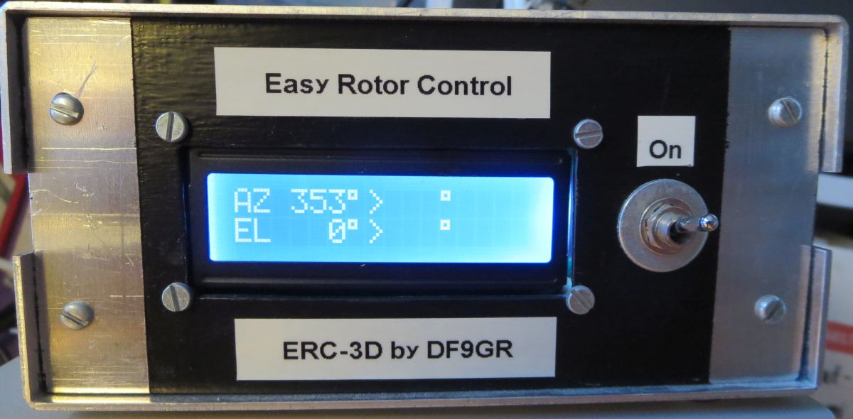
Rotor controller The LCD
display shows the current rotor position to the left and the
new position to the right. Each rotor's position is also displayed in PstRotator.
|
|
|
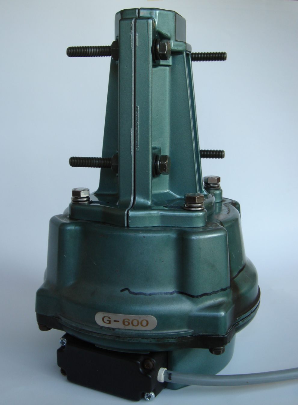
Azimuth
rotator I bought the rotator on Ebay. It was in good working order, but I had to renew the 500 ohm potentiometer inside the house. The Yaesu
control box serves as a power supply for the rotator motor. The control box also applies 5 V DC to the rotator potentiometer. The voltage on the pot's
wiper is connected to the ERC-3D controller via a wire in the rotator cable. The ERC-3D calculates the antenna position by measuring the wiper voltage. The wiper voltage is proportional to the position of
the antenna. 0.07 V corresponds to 0 degrees, and 4.60 V corresponds to 360 degrees. |
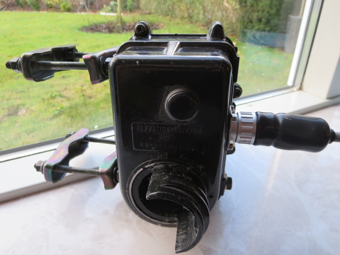 | Elevation rotator Maintenance due to age: I've cleaned the rotator inside, and replaced all balls in the bearings. The 500 ohm potentiometer inside the rotator was renewed.. The Kenpro control box serves as a power supply for the rotator motor. I've added a 5V DC PSU inside the control box. This voltage is fed to the rotator potentiometer. The voltage on the potentiometer's wiper is measured by the ERC-3D controller as it indicates the elevation angle. |
Written by OZ1BXM
Lars Petersen. Latest revision 19-July-2023.